3D Scanning for Casting Inspection and Deformation Analysis
A cast aluminum housing can appear acceptable after shakeout and cleaning, yet still create problems at the machining center. A flange may have lifted slightly during cooling, a bearing boss may have shifted relative to the mounting face, or a thin wall may no longer have enough stock for the specified finishing operation. None of these conditions necessarily produces an obvious visual defect.
3D scanning for casting inspection helps engineers measure these geometric differences before they become expensive machining or assembly problems. By comparing the accessible as-cast surface with an appropriate CAD reference, manufacturers can evaluate dimensional deviations, identify deformation patterns, and investigate whether sufficient machining allowance remains in critical areas.
The challenge is interpreting the data correctly. A deviation color map can reveal where a casting differs from its reference geometry, but it does not automatically explain why the difference occurred. Likewise, a casting that looks close to nominal after best-fit alignment may still be poorly positioned relative to its intended machining datums.
For a foundry or machining supplier, the useful question is not simply whether the casting can be scanned. It is whether the inspection result supports a practical decision: release the casting for machining, investigate a dimensional trend, adjust a process, or reject a part that cannot meet the finished requirements.
What Should Be Measured on an As-Cast Component?
Before planning a scan, engineers need to distinguish the geometry of the casting blank from the geometry of the finished component. The two may be represented by different CAD models and governed by different dimensional requirements.
A raw casting intentionally contains additional material on surfaces that will be machined. It may also have draft angles, parting-line features, fillets, and surface texture that disappear or change during subsequent processing. Comparing every point on an as-cast component directly against the finished-part CAD model can therefore produce a visually dramatic deviation map without identifying a genuine manufacturing problem.
The preferred reference is an approved as-cast model or a documented inspection definition that accounts for the intended stock allowance and casting tolerances. If only the finished-part CAD model is available, the comparison must explicitly account for which surfaces are intended to remain as cast and which will be machined.
| Inspection Characteristic | What It Reveals | Manufacturing Significance |
|---|---|---|
| Overall dimensions | Length, width, height, and spacing changes | Indicates dimensional conformity and potential tooling or process variation |
| Surface profile | Local differences between the casting and reference geometry | Highlights displaced walls, ribs, bosses, and curved surfaces |
| Warpage and distortion | Bending, twisting, or nonuniform geometric change | May affect fixture seating, machining setup, and assembly |
| Machining allowance | Available stock relative to planned finished surfaces | Helps identify areas that may not clean up during machining |
| Feature displacement | Changes in the location of bosses, flanges, and accessible locating features | Can affect datum establishment and subsequent machining operations |
For example, a cast transmission housing may have a broad mounting flange, several bearing bosses, and a network of reinforcing ribs. The flange and bosses may be critical to the machining setup, while the ribs are primarily evaluated for overall shape and clearance. Applying the same inspection method and tolerance interpretation to every surface would not reflect their different functions.
Measurement priorities should follow the drawing, the casting process, and the planned manufacturing route. A large deviation on a nonfunctional exterior surface may be less important than a smaller displacement at a locating boss that determines the machining coordinate system.
How to Inspect a Casting with 3D Scanning
Reliable casting dimensional inspection depends on a controlled sequence of preparation, acquisition, alignment, and evaluation. The scanner produces surface measurements, but the inspection plan determines whether those measurements can answer the engineering question.
Prepare the Casting and Control Its Measurement Condition
Loose sand, residual coating, dirt, and unstable burrs can interfere with surface measurement. The casting should be cleaned to the condition specified by the inspection procedure, without removing material that must remain part of the evaluated geometry.
Temperature also matters. A casting measured shortly after a thermal process may not have reached a stable condition. Thermal expansion and transient temperature gradients can influence its dimensions, particularly on large components or when tight tolerances are involved.
Thin-walled castings require special attention to support. A housing placed on three support points may assume a different shape from the same housing clamped against a fixture. Neither condition is universally correct; the appropriate setup depends on whether the drawing or inspection plan requires a free-state measurement or a specified restrained condition.
Record the support arrangement, part orientation, and relevant environmental conditions. Without a consistent setup, apparent batch-to-batch deformation may partly reflect differences in how the components were measured.
Capture the Accessible Casting Geometry
Castings frequently contain curved walls, reinforcing ribs, pockets, and recessed features. These surfaces make a single-view scan insufficient for many inspection tasks.
Plan the acquisition around the regions that influence the decision. If the objective is to assess flange warpage, the flange and its surrounding support geometry need reliable coverage. If the objective is to evaluate machining stock around a bearing seat, the relevant raw surfaces and positioning features must be captured.
Multiple scan positions may be required to observe opposing sides or recessed areas. Their data must be registered into a consistent coordinate system. Registration quality becomes especially important when the measured characteristics span different scan positions or opposite sides of a large component.
Rough casting texture can create local variation in the measured points. Reflective machined patches, dark surfaces, and steep viewing angles may also affect optical acquisition. Increasing point density alone does not resolve poor optical visibility or systematic registration error.
Inspect the data before analysis. A complete-looking mesh can contain interpolated regions or filtered surfaces that should not be treated as direct measurements. For dimensional inspection, preserve a clear distinction between observed geometry and reconstructed geometry.
Align the Casting to the Correct Reference
Alignment is one of the most consequential decisions in casting inspection. The same scan can produce noticeably different deviation patterns depending on how it is positioned relative to the CAD model.
Best-fit alignment generally seeks a transformation that minimizes a defined measure of mismatch between selected measured points and reference geometry. It is useful for assessing overall shape agreement, but it can redistribute apparent deviations across the casting.
Datum-based alignment instead establishes the coordinate relationship using designated reference features or a specified datum reference frame. This is often more relevant when the inspection concerns machining setup, locating surfaces, or assembly relationships.
Consider a housing with a displaced bearing boss. A broad best-fit alignment may reduce the apparent mismatch around that boss by allowing the entire casting to shift slightly relative to the CAD model. A datum-based alignment tied to the intended locating features may reveal a larger and more functionally meaningful displacement.
Neither alignment method is inherently superior for every task. The appropriate method depends on what is being evaluated.
| Inspection Objective | Alignment Consideration |
|---|---|
| Evaluate overall shape differences | A controlled best-fit comparison may be informative |
| Check features relative to functional datums | Use the specified datum-based evaluation |
| Assess machining stock | Use a setup that represents the intended machining location and orientation |
| Compare multiple production batches | Apply a consistent, documented alignment procedure |
When machining datums have not yet been created, the inspection plan must identify how the raw casting will be located. Suitable casting pads, accessible reference features, or a defined fixture may provide a practical basis, but their measurement uncertainty and relationship to the intended machining setup must be considered.
Evaluate the Deviations, Not Just the Color Map
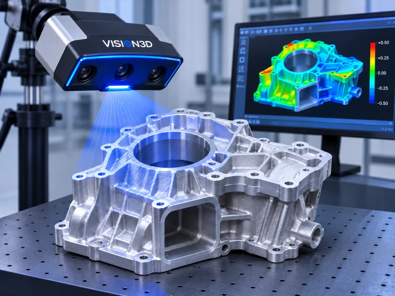
After alignment, inspection software can calculate distances between measured surfaces and the reference geometry. The resulting color map is useful for locating broad patterns of positive and negative deviation.
However, a color map should be treated as a starting point. Its interpretation depends on the alignment, the distance calculation, the sign convention, the color scale, and the geometry selected for comparison.
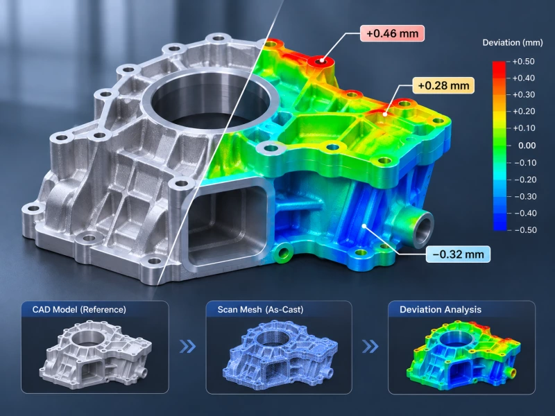
For a cast housing, a red region near a flange may indicate that the measured surface lies outside a selected positive deviation limit. It does not, by itself, establish that the flange is warped or that the casting must be rejected. A rigid-body displacement, incorrect reference model, or inappropriate alignment could produce a similar appearance.
Supplement the surface map with measurements that correspond to the inspection requirements: distances between features, selected cross-sections, plane relationships, local surface profiles, and dimensional results tied to the applicable datums.
Where the required functionality is available and validated, inspection software such as VisionInspect can form part of a scan-to-CAD dimensional inspection workflow. The suitability of any specific evaluation should be confirmed against the software's supported measurement functions and the applicable drawing requirements.
Measuring Casting Shrinkage and Deformation
Dimensional changes in castings are influenced by material behavior, tooling, solidification, cooling, restraint, and subsequent processing. Optical scanning can quantify the resulting surface geometry, but the measured shape alone rarely identifies a single root cause.
That distinction is important when inspection data is used to guide process corrections.
Distinguishing Overall Shrinkage from Local Distortion
Shrinkage refers broadly to dimensional contraction associated with cooling and phase changes during casting. Foundry engineers account for expected contraction when designing patterns and tooling, but actual behavior depends on alloy, geometry, process conditions, and local restraint.
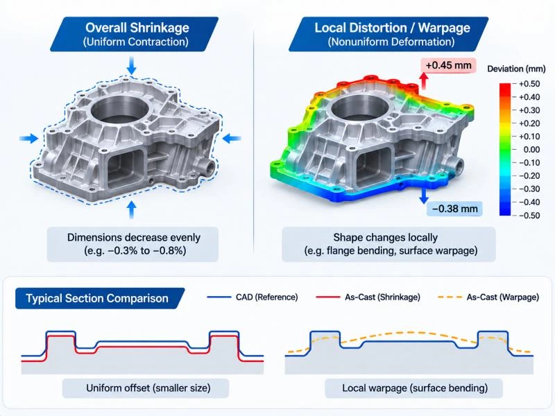
In a simplified case, a component that contracts nearly uniformly may show dimensional changes distributed across several directions. Local distortion is different: one flange may bend, a thin wall may bow, or two bosses may move relative to each other.
Both effects can exist in the same casting. A housing may be smaller than its nominal envelope while also exhibiting localized warpage near a thick-to-thin section transition.
To distinguish these conditions, examine more than a single surface map. Compare distances between selected features, evaluate cross-sections, and inspect the displacement of critical regions relative to a consistent reference.
A nearly uniform change in several measured dimensions may suggest a broader contraction trend. A localized change concentrated around a flange or rib may suggest differential deformation. These are diagnostic clues, not proof of the underlying process mechanism.
Confirming the cause may require information about alloy composition, mold or die temperature, feeding conditions, cooling history, heat treatment, and mechanical restraint.
Detecting Warpage in Thin-Walled Castings
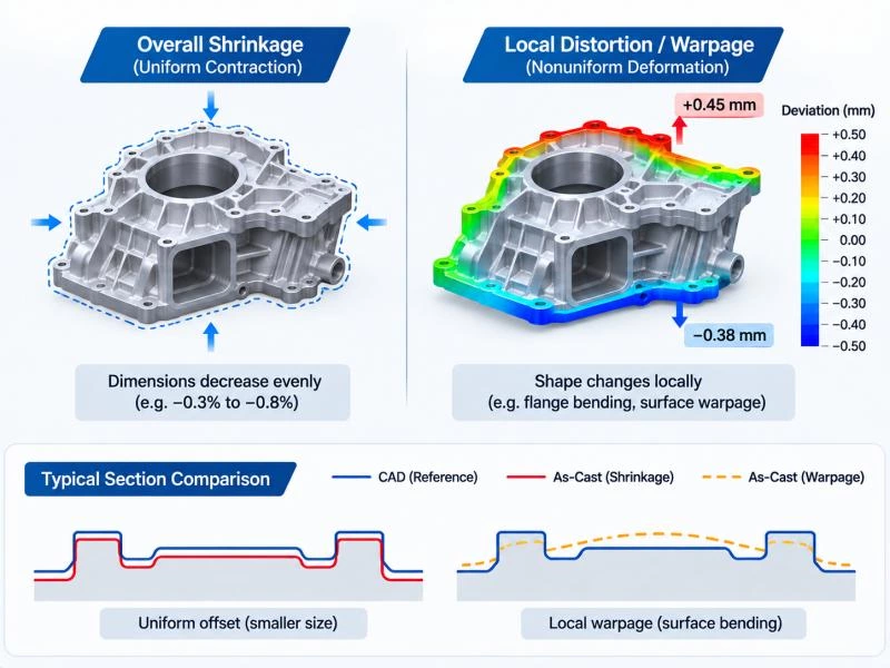
Thin walls and broad flanges are often sensitive to nonuniform cooling and restraint. A component may twist or bow as different regions contract, particularly when its geometry contains large changes in section thickness.
For a cast aluminum housing, the inspection plan might evaluate the relative height of several points along a flange, the profile of the mounting surface, and the location of nearby bosses.
A useful method is to inspect the same casting in a defined support condition and compare selected cross-sections with the approved reference geometry. This helps distinguish localized bending from an overall change in part orientation.
Care is needed when a best-fit plane is used. Fitting a plane to a warped surface can distribute the deviations around that plane, making the result appear more balanced without removing the underlying form error.
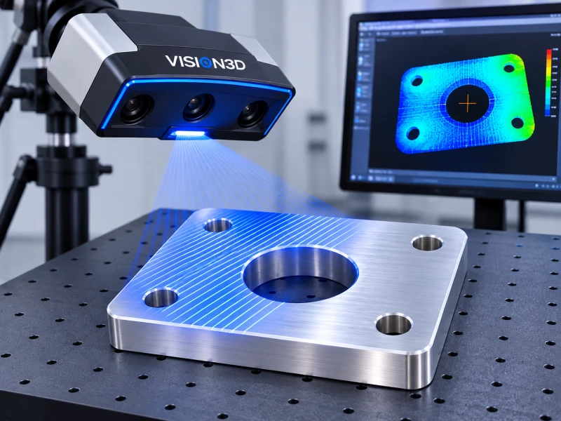
If the requirement concerns flatness, evaluate the measured surface using the appropriate flatness criterion rather than interpreting the colors from a general CAD alignment as a direct flatness result. The same principle applies to other geometric characteristics.
For castings that will be clamped during machining, it may be useful to compare free-state and restrained-state geometry. A flange that moves into position under clamping may still create machining or residual-stress concerns, depending on the application. Both states should be documented rather than mixed in a single dataset.
Comparing Deformation Across Production Batches
A single scan describes one component at one measurement condition. Repeated measurements across production batches can reveal whether a dimensional deviation is isolated or systematic.
Suppose a foundry observes that the distance between two bearing bosses gradually changes over several production runs. If the same inspection setup and datum procedure are used, the trend may justify investigation of tooling condition, process stability, or thermal behavior.
For meaningful comparison, the measurement procedure should remain consistent. Changes in part support, alignment, filtering, or the selected reference model can introduce artificial variation.
Track the actual dimensions and relevant geometric characteristics, not only the percentage of points displayed in a particular color. A stable color-map appearance can conceal changes in a critical feature, while a large colored region on a nonfunctional surface may have little effect on acceptance.
Where appropriate, use statistical process-control methods to monitor selected characteristics over time. Scanning supplies the measurement observations; the statistical analysis helps determine whether the process behavior is stable and whether a change warrants investigation.
Checking Machining Allowance Before CNC Machining
One of the most valuable applications of 3D scanning for casting inspection is determining whether a raw casting contains sufficient material for the planned machining operations.
A casting can satisfy a broad envelope requirement and still fail to clean up at a critical surface. The problem is often not the total amount of material in the part, but where that material lies relative to the intended machining coordinate system.
Why a Standard CAD Deviation Map Is Not Enough
Machining allowance is the stock available between the raw casting surface and the intended finished surface, evaluated in a direction relevant to the machining operation.
A conventional surface deviation map typically reports distances between the measured and reference surfaces according to a selected comparison method. Those distances are not automatically equivalent to the stock that a cutting tool will remove.
For example, the shortest distance from a raw surface to a CAD surface may differ from the distance along the planned tool approach direction. This difference becomes important on angled faces, curved surfaces, and complex housing geometry.
The analysis must also account for how the casting will be located in the machining fixture. Translating or rotating the raw casting within its permitted setup conditions can redistribute the available stock among several features.
Moving the setup to improve allowance on one bearing seat may reduce allowance on another. The correct objective is therefore to satisfy all relevant machining and finished-part constraints, not simply to maximize stock at one location.
A Simplified Machining Allowance Example
Consider a cast aluminum housing with a flange that will be finish-machined. The planned machining setup defines the target finished plane, and the measured raw surface is evaluated along the machining direction.
The following figures are illustrative. They are intended to demonstrate the evaluation method, not to describe an actual production casting.
| Inspection Location | Available Stock | Minimum Required Stock | Assessment |
|---|---|---|---|
| Region A | 2.40 mm | 1.50 mm | Above minimum |
| Region B | 1.85 mm | 1.50 mm | Above minimum |
| Region C | 1.20 mm | 1.50 mm | Below minimum |
| Region D | 2.10 mm | 1.50 mm | Above minimum |
Region C has only 1.20 mm of stock, compared with a specified minimum of 1.50 mm. Under the assumed setup and allowance criteria, the shortfall is:
Allowance Shortfall = 1.50 − 1.20 = 0.30 mm
That result identifies a potential cleanup problem. It does not necessarily mean the entire casting must be scrapped immediately.
The manufacturing engineer may investigate whether an approved setup adjustment can recover sufficient stock while preserving the required finished dimensions. The engineer must also consider stock distribution on other surfaces, fixture constraints, machining forces, and the remaining wall thickness after machining.
If no permissible setup can satisfy all required surfaces, the casting may need to be rejected or evaluated under an approved engineering disposition.
Machining Allowance Is a Multi-Surface Problem
On a complex housing, several machined features may be functionally related. Bearing bores, gasket faces, locating pads, and mounting holes cannot always be adjusted independently.
A robust allowance evaluation therefore considers the casting as a whole. The raw geometry is positioned within the constraints of the intended machining setup, and the available stock is checked across all critical surfaces.
Particularly for large castings, this analysis can help avoid spending machining time on blanks that cannot produce acceptable finished components.
It can also provide useful feedback to the foundry. Repeated stock shortages in the same region may indicate a consistent geometric displacement that deserves further investigation.
However, optical surface measurements cannot establish the presence or absence of hidden internal defects or guarantee the final wall thickness where the internal surface is inaccessible. Additional measurement or nondestructive testing may be needed for those requirements.
How to Interpret Casting Deviation Maps Correctly
Deviation maps are among the most recognizable outputs of 3D inspection, but they are also easy to misinterpret.
A map with broad green areas may suggest good agreement with the reference. Yet the result depends on the chosen alignment, tolerance display limits, color scale, and the regions included in the comparison.
Three questions should be answered before drawing a manufacturing conclusion.
What Does the Color Actually Represent?
Most surface comparison displays assign colors to signed or unsigned geometric deviations according to the software's settings. Positive and negative values may indicate opposite directions relative to the reference surface, but the precise sign convention must be checked.
A color scale of ±1.00 mm presents the same geometric data very differently from a scale of ±0.10 mm. Changing the display range does not change the casting; it changes how strongly the deviations appear in the visualization.
For this reason, inspection reports should include numerical values and the applicable limits rather than relying solely on screenshots of colored geometry.
Could Alignment Be Hiding the Problem?
Imagine a casting with one displaced mounting boss and a broad exterior surface that otherwise matches the reference well.
Using a best-fit alignment over the entire exterior may slightly rotate or translate the scan to reduce overall mismatch. The resulting map may distribute the error over several regions.
When the casting is aligned to its intended locating datums, the boss displacement may become more apparent. The two maps are not necessarily contradictory; they answer different measurement questions.
For dimensional acceptance, the alignment must follow the inspection requirement. For process investigation, multiple controlled alignment strategies can sometimes provide useful complementary information, provided their purposes are clearly distinguished.
Does the Surface Deviation Explain the Cause?
Not by itself.
A localized positive deviation could result from excess material, a tooling change, an alignment issue, or another manufacturing influence. A bowed flange could be associated with differential cooling, subsequent heat treatment, fixture restraint, or mechanical handling.
3D scanning provides evidence of the final geometry. Root-cause analysis requires additional process knowledge and, when appropriate, measurements taken at different production stages.
This distinction prevents a common mistake: making a tooling correction based on a single color map before verifying that the measurement setup and reference geometry are correct.
When 3D Scanning Is Not Enough for Casting Inspection
Optical 3D scanning measures surfaces that can be observed by the instrument under suitable acquisition conditions. It is not a universal casting defect detection method.
Surface geometry may reveal an open cavity, a visible crack-like feature, or a deformation associated with a manufacturing problem. However, detecting an external indication is not the same as determining the nature or full extent of the underlying defect.
Internal shrinkage porosity, enclosed gas pores, and hidden cracks generally require appropriate nondestructive examination methods, such as industrial computed tomography, radiography, or other methods selected for the material and defect type.
Similarly, narrow internal passages and deeply recessed features may not be sufficiently visible to an optical scanner. Their inspection may require contact measurement, internal scanning methods, or other suitable techniques.
| Inspection Requirement | Role of Optical 3D Scanning | Possible Additional Method |
|---|---|---|
| External casting profile | Measures accessible surface geometry | Reference measurement where needed |
| Flange warpage | Supports surface form and deformation evaluation | Independent dimensional verification |
| Machining stock on visible surfaces | Supports geometric allowance analysis | Machining setup verification |
| Internal porosity | Cannot directly characterize enclosed pores | Industrial CT or radiography |
| Hidden internal passage geometry | Limited by optical accessibility | CT, suitable probing, or other internal measurement |
Measurement capability must also be considered relative to the tolerance. A scanner that provides useful full-field information on a rough casting may not be the best instrument for every tightly toleranced finished bore or precision datum feature.
The appropriate inspection strategy may combine optical scanning for broad surface coverage with other measurement methods for selected characteristics. The objective is reliable dimensional evidence, not exclusive use of one technology.
Using Casting Inspection Data to Improve Production
The value of casting dimensional inspection increases when measurement results are connected to manufacturing decisions.
During process development, scanning can reveal whether the produced geometry differs systematically from the approved casting reference. Engineers can then investigate whether tooling compensation, casting conditions, or downstream operations need attention.
For recurring production, selected dimensional characteristics can be monitored across batches. A stable process may still produce individual nonconforming parts, while a gradual trend may indicate that process behavior is changing before widespread failures occur.
When investigating a recurring deviation, it is useful to preserve the relationship between the measurement result and the manufacturing record. Relevant information may include tooling identification, production batch, process conditions, inspection setup, and any subsequent machining results.
For example, if several batches show reduced machining stock near the same flange corner, the foundry and machining team can review whether the condition correlates with a particular tool, cooling arrangement, or locating method. The scan identifies where the dimensional problem occurs; the production record helps investigate why.
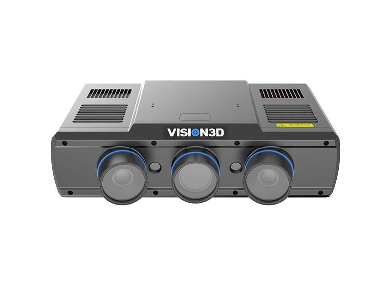
On the equipment side, the PowerScan Series is a relevant starting point for discussing industrial optical scanning requirements. Selection should be based on casting size, surface characteristics, accessibility, measurement volume, and the accuracy required by the inspection plan.
For production teams considering a repeatable inspection workflow, the important questions extend beyond acquisition speed. Part loading, datum establishment, feature evaluation, reporting, operator variation, and measurement verification all influence whether the process can be used reliably in routine manufacturing.
Not every casting needs a full-surface scan at every production stage. A practical inspection strategy may use comprehensive measurements during process development and targeted checks during stable production, depending on risk, customer requirements, and process capability.
Conclusion
3D scanning for casting inspection is most useful when it turns complex surface geometry into information that engineers can act on. A well-planned measurement can reveal where a casting differs from its approved reference, how its shape has changed, and whether critical regions contain sufficient material for subsequent machining.
Accurate interpretation requires more than a detailed point cloud. The reference model, alignment method, support condition, feature evaluation, and measurement uncertainty all influence the result. Shrinkage and deformation patterns can guide investigation, but they should not be mistaken for definitive proof of a particular casting-process fault.
For foundries and machining suppliers working with complex cast components, combining appropriate 3D scanning with a verified inspection procedure can support earlier dimensional decisions and more consistent production feedback.
To discuss casting geometry, machining allowance, or dimensional inspection requirements, contact the VISION3D engineering team with your part drawings, casting dimensions, and inspection objectives.
Frequently Asked Questions
Can 3D scanning detect casting shrinkage and deformation?
3D scanning can measure accessible casting surfaces and compare them with an appropriate reference to quantify dimensional changes and deformation. Patterns in the data may suggest shrinkage or warpage, but identifying the underlying cause requires additional process information and engineering analysis.
How does 3D scanning help check machining allowance?
Measured as-cast geometry can be compared with planned finished surfaces in a coordinate system representing the intended machining setup. This allows engineers to evaluate available stock at critical locations and identify areas that may not clean up during machining. The evaluation must account for setup constraints, machining direction, and other required surfaces.
Can an optical 3D scanner detect internal casting defects?
Not directly when the defects are enclosed within the material. Optical scanners primarily measure visible surface geometry. Internal porosity, hidden shrinkage cavities, and other subsurface defects generally require suitable nondestructive examination methods, such as industrial CT or radiography.
What causes errors in casting dimensional inspection?
Potential influences include unstable part temperature, inconsistent support, incomplete surface coverage, registration error, unsuitable alignment, incorrect reference geometry, and measurement uncertainty. A documented inspection procedure helps control these influences and makes results more comparable across parts and batches.
Should castings be compared with the as-cast CAD model or the finished-part model?
For general casting conformity, an approved as-cast reference is usually more appropriate because it accounts for intended stock allowance and casting-specific geometry. A finished-part model can support machining allowance analysis, but the evaluation must distinguish material that is intentionally left for machining from actual dimensional nonconformity.