3D Scanner Accuracy, Resolution & Repeatability Explained
Two industrial 3D scanners can produce point clouds that look almost identical yet return different dimensional measurements. One may capture a narrow groove with more detail, while the other produces results closer to a calibrated reference. A third system may deliver nearly identical measurements every time without being particularly accurate.
These differences come down to three specifications that are frequently confused: 3D scanner accuracy, resolution, and repeatability. All three matter in dimensional inspection, but they answer different questions. Accuracy concerns measurement error. Resolution determines how much geometric detail can be captured. Repeatability describes the consistency of repeated measurements under defined conditions.
For manufacturers inspecting machined parts, automotive components, tooling, or large assemblies, understanding these distinctions is important when comparing equipment. A specification that looks impressive on paper may have limited value if it does not address the dimensions, tolerances, and inspection conditions of the actual part.
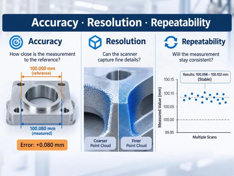
Accuracy, Resolution, and Repeatability in 3D Scanning
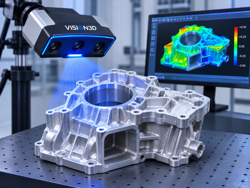
The easiest way to understand these parameters is to consider a machined aluminum housing with mounting holes, narrow grooves, and curved surfaces. The housing needs to be scanned and compared with its engineering drawing or CAD model.
The scanner must capture enough surface detail to represent the grooves and edges. It must also measure the relevant dimensions with sufficiently low error. If the housing is inspected repeatedly during production, the measurements need to remain consistent from one inspection to the next.
These requirements are related, but improving one does not necessarily improve the others.
Accuracy: How Close Is the Measurement to the Reference?
3D scanner accuracy concerns the agreement between a measured value and a reference value. In practical inspection work, engineers evaluate measurement error by comparing scanner results with calibrated dimensions or suitable reference measurements.
Suppose a calibrated reference length is 100.000 mm and the scanner reports 100.080 mm. The signed measurement error is +0.080 mm. That result describes one measurement under a particular set of conditions; it does not establish the accuracy of the entire scanner across every feature or measurement position.
Published accuracy specifications are also conditional. A manufacturer may determine performance using calibrated spheres, length standards, or other artifacts under specified testing procedures. Measuring a polished casting, a deep cavity, or a large mechanical assembly can introduce additional sources of error that are not fully represented by a single specification value.
Resolution: Can the Scanner Capture the Required Detail?
Resolution describes the ability to distinguish small geometric features. It is often discussed alongside point spacing, but the two terms are not identical. Point spacing describes the distance between neighboring sampled points; actual feature resolution also depends on the optical system, surface conditions, noise, and reconstruction methods.
Consider a component containing a narrow groove. A scanning configuration with 0.05 mm point spacing may represent the groove more clearly than one using 0.20 mm spacing. However, finer sampling does not guarantee that the groove dimensions are more accurate. Both scans may still contain calibration errors, optical distortions, or incomplete surface data.
Small holes, sharp edges, and steep surface transitions can be especially challenging. Even a high-resolution scanner cannot reliably capture a feature that is hidden from its cameras or illumination system.
Repeatability: Will the Measurement Stay Consistent?
Repeatability is a specific aspect of measurement precision. It describes the agreement between repeated results obtained under defined repeatability conditions, generally involving the same equipment, procedure, operator, location, and a short measurement interval.
For production inspection, repeatability matters because engineers need to distinguish genuine changes in manufactured parts from variation introduced by the measurement process.
A scanner can be highly repeatable and still produce measurements that differ consistently from a calibrated reference. For example, five independent measurements of a 100.000 mm reference might produce the following results:
| Scan | Measured Length | Error |
|---|---|---|
| 1 | 100.098 mm | +0.098 mm |
| 2 | 100.101 mm | +0.101 mm |
| 3 | 100.100 mm | +0.100 mm |
| 4 | 100.099 mm | +0.099 mm |
| 5 | 100.102 mm | +0.102 mm |
Illustrative measurement data only; not actual scanner test results.
The measurements have a narrow spread, but their average is 100.100 mm, or 0.100 mm above the reference. The system is consistent under these test conditions, yet the results contain a systematic deviation.
Repeated measurements should therefore be assessed alongside their agreement with reference values. A small standard deviation cannot compensate for an unacceptable measurement bias.
Comparing the Three Parameters
| Parameter | What It Tells You | Typical Inspection Concern |
|---|---|---|
| Accuracy | Agreement with a reference value | Dimensional measurement error |
| Resolution | Ability to distinguish geometric details | Small grooves, edges, and surface features |
| Repeatability | Consistency under repeated measurement conditions | Measurement stability during routine inspection |
Precision is the broader concept describing the agreement among repeated measurements; repeatability is precision evaluated under a particular set of conditions.
For industrial inspection, these specifications should be considered together with measurement uncertainty. A scanner must not only capture the required geometry but also support reliable decisions about whether a manufactured part meets its tolerances.
Why Higher Resolution Does Not Mean Better Accuracy
Increasing point cloud density can make a scanned model appear more detailed. Fine surface transitions become easier to see, and small geometric features may be represented by more measurement points. However, additional points do not automatically improve the dimensional reliability of the result.
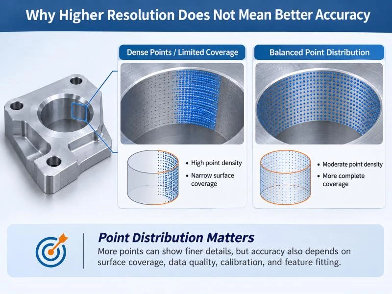
Consider two scans of the same cylindrical feature. One contains thousands of points concentrated on a limited portion of the cylinder. The other contains fewer points distributed more evenly around the accessible surface. Depending on the measurement conditions, the second dataset may support a more stable cylinder fit, even though it contains fewer points.
The problem is not simply the number of measurements. Their distribution, quality, and relationship to the geometric feature also matter.
Systematic errors are another limitation. If a scanner has a scale-related measurement deviation, collecting more points does not remove it. Reflective surfaces may also generate noisy or unreliable data, regardless of sampling density.
Inspection software introduces further considerations. Planes, cylinders, and spheres are commonly calculated by fitting geometric models to scanned points. Filtering, point selection, and fitting methods can change the reported dimensions. Excessive smoothing may suppress actual surface deviations, while an inappropriate fitting method may produce a result that does not match the drawing's evaluation requirements.
Higher resolution is valuable when the part contains features that require it. For broad surfaces and larger geometric characteristics, collecting unnecessarily dense data may increase scanning and processing time without improving the inspection decision.
Measurement Accuracy Across Different Part Sizes
Measuring a small machined bracket is not the same as inspecting a two-meter automotive assembly. A compact part may fit within a single scanning field, while a large structure often requires several scanning positions and a common coordinate reference.
For the larger component, engineers may need to measure distances between mounting points located far apart. Local surface detail is still important, but the measurement system must also preserve dimensional relationships across the working volume.
Volumetric accuracy concerns measurement performance throughout a defined three-dimensional measurement volume. Its evaluation depends on the system configuration, measurement range, and applicable test procedure. It should not be assumed from a local accuracy specification alone.
Multiple-scan inspection introduces additional challenges. When point clouds are combined using overlapping geometry or reference targets, registration uncertainty can affect the final measurement. Scale errors, coordinate transformations, and the spatial distribution of reference information may also influence dimensions measured across a large assembly.
For example, a scanner may produce satisfactory measurements on a small aluminum housing but require a different verification approach when inspecting an automotive body structure. A short reference length cannot, by itself, demonstrate performance across the full measurement volume.
Some industrial measurement systems report length-dependent performance characteristics. Others use different specifications and test methods. Engineers should examine the stated measurement range and evaluation procedure before comparing numerical accuracy values from different systems.
What Affects 3D Scanner Measurement Results?
A scanner's published specifications describe performance under defined conditions. On a production floor, however, measurement results are influenced by the part, the surrounding environment, the scanning procedure, and the way the captured data is evaluated.
Temperature is one of the less obvious sources of measurement error. A machined metal component can expand or contract as its temperature changes, while temperature variations may also affect the measurement equipment. For a part with tight dimensional tolerances, these changes can become significant. Calibration and verification procedures should therefore be considered alongside the environmental conditions in which inspection takes place.
Surface properties create a different set of challenges. Polished aluminum, dark materials, and highly reflective surfaces may produce uneven or insufficient optical signals. A scanner can capture most of a component successfully while leaving small areas with missing or noisy points. Adjusting exposure, changing scanning positions, or using an appropriate surface treatment may help, although any applied coating must be considered when evaluating dimensional accuracy.
Geometry matters just as much as material. Deep holes, narrow channels, and surfaces hidden behind other features may not be visible to the scanner's cameras or illumination system. When the available data covers only a limited portion of a geometric feature, the calculated dimensions can become less stable.
For example, a cylinder fitted from a narrow strip of visible surface may be more sensitive to point distribution and measurement noise than one fitted using a broader, well-distributed surface region. Increasing point density in the same limited area does not necessarily solve the problem.
Alignment Can Change the Inspection Result
Once the scan is complete, the point cloud must often be registered, aligned with a CAD model, and evaluated against engineering requirements. The alignment method can have a substantial effect on the reported deviations.
A best-fit alignment attempts to minimize differences between measured geometry and a reference model. Although useful for certain surface comparisons, it does not necessarily reproduce the datum reference system defined on an engineering drawing.
Consider a machined housing inspected for the position of several mounting holes. If the scan is aligned using an overall best fit rather than the specified datums, the resulting position measurements may not reflect the intended GD&T requirements. The underlying point cloud has not changed, but the reported deviations can be different.
Software used for dimensional inspection, including VisionInspect, should therefore be evaluated as part of the complete measurement process. Reliable results depend on suitable data acquisition, feature extraction, alignment, and reporting procedures rather than scanner hardware alone.
How to Check 3D Scanner Accuracy Before Production Use
Accuracy verification should begin with the measurement task, not with the scanner specification sheet. Engineers need to identify which dimensions matter, how those dimensions will be evaluated, and what level of measurement uncertainty is acceptable for the inspection decision.
A practical assessment usually involves two different types of testing. Calibrated reference artifacts help evaluate defined measurement characteristics, while representative production components reveal problems that may arise from actual materials, geometries, and scanning procedures.
Start with a Calibrated Reference
Calibrated spheres, ball bars, length standards, and other suitable reference artifacts provide known dimensions for comparison. The selected artifact should match the measurement characteristic and working range being evaluated.
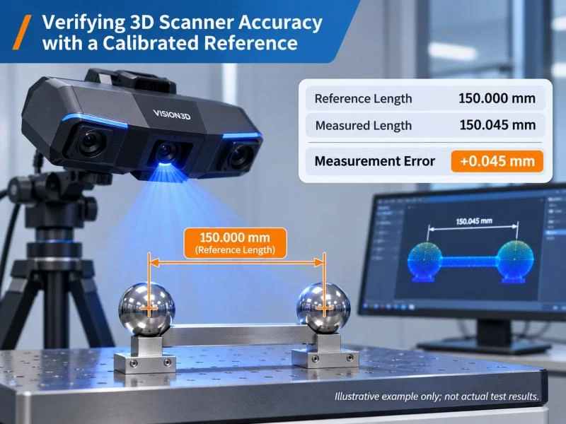
For example, a scanner may measure the distance between two calibrated sphere centers. Comparing the measured distance with the certified reference value provides a length measurement error for that particular setup.
The calculation is straightforward:
Measurement Error = Measured Value − Reference Value
If a calibrated length is 150.000 mm and the scanner reports 150.045 mm, the signed error is +0.045 mm. The result should be documented together with the reference uncertainty, measurement conditions, and evaluation procedure.
One successful measurement does not establish performance throughout the scanner's working range. Where appropriate, reference measurements should cover different positions, orientations, and lengths relevant to the intended application.
Repeat the Entire Measurement, Not Just the Calculation
Repeatability testing should include independent scans of the same reference artifact or representative component. Recalculating a dimension several times from one stored point cloud does not capture the variation introduced by repeated data acquisition.
The operator, equipment configuration, measurement procedure, and environmental conditions should remain consistent during a repeatability test. The resulting measurements can then be examined using their average, range, and standard deviation.
When a scanner is intended for routine production inspection, further testing may be necessary. Changes in operators, part positioning, environmental conditions, or equipment setup can introduce variation that is not captured by a controlled repeatability test.
Verify the Scanner on Real Production Parts
Reference artifacts cannot reproduce every difficulty encountered during production inspection. A polished casting, a component with deep recesses, or a large assembly requiring several scans may behave differently from a calibrated standard.
For a manufacturer inspecting aluminum housings, a useful application test would include representative parts with mounting holes, machined planes, and curved features. The scanner would capture the required geometry, and the extracted dimensions would be compared with suitable reference measurements obtained through an established metrology process.
The evaluation should examine more than dimensional differences. Engineers should also determine whether the required features are consistently captured, whether alignment remains stable, and whether the inspection can be completed within the available production cycle time.
Applicable technical guidelines, including relevant parts of VDI/VDE 2634 and the ISO 10360 series, may provide a framework for evaluating particular measurement systems. Their applicability depends on the equipment and test method. Before comparing scanner specifications, buyers should request documentation identifying the actual procedure and measurement characteristics used.
Choosing a 3D Scanner for Your Inspection Requirements
The correct scanner is not necessarily the one with the smallest published accuracy figure. Selection should begin with the engineering drawing and the inspection task: the dimensions to be checked, the tolerances involved, the smallest relevant features, and the overall size of the component.
A part with a dimensional tolerance of ±0.05 mm generally places greater demands on the measurement process than one with a tolerance of ±0.50 mm. Yet a scanner advertised with a 0.02 mm accuracy specification cannot automatically be considered suitable for the tighter tolerance.
The published value may describe a particular performance test rather than the measurement uncertainty of the complete inspection process. Scanning conditions, feature fitting, alignment, reference uncertainty, and the method used to determine conformity must all be considered.
Engineers should establish an appropriate relationship between measurement uncertainty and the specified tolerance. A suitable decision rule is also necessary when measured values approach the tolerance limits. A measurement falling inside the dimensional limits does not, by itself, guarantee that the actual part conforms.
Different Inspection Tasks Require Different Priorities
For precision-machined components, dimensional accuracy and reliable geometric feature extraction are often the primary concerns. Small holes, planes, and cylindrical features should be tested using representative parts, particularly when tolerances are tight.
Freeform surfaces introduce different requirements. Complete surface coverage and sufficient geometric detail may be more important than collecting the maximum possible number of points. Engineers should examine how consistently the scanner captures curved regions and how the resulting data performs during CAD comparison.
Large assemblies require attention to measurement volume, coordinate registration, and dimensional relationships between distant features. In these applications, verification across the intended working range is particularly important.
High-volume production inspection places additional emphasis on repeatability and cycle time. A system that performs well during a controlled demonstration must also be capable of producing stable results under the intended production conditions.
Evaluate the Complete Scanning Workflow
Equipment configuration should reflect how the scanner will actually be used. A system intended for occasional engineering measurements may have different requirements from one operating as part of an automated inspection process.
For detailed surface acquisition and dimensional evaluation, the PowerScan Series can be considered alongside the required part dimensions, surface characteristics, and measurement performance.
Where repeated inspection and automated operation are priorities, the AutoScan Series offers another category of equipment to evaluate. Automation can help standardize scanning procedures, although repeatability and inspection cycle time still need to be verified for the specific application.
Software capabilities should be assessed at the same time as the scanner. CAD comparison, datum alignment, feature evaluation, and inspection reporting all influence whether the captured data can support the required quality-control decisions.
Before purchasing, manufacturers should arrange an application-specific demonstration using representative components. The most useful comparison is not simply which scanner produces the densest point cloud, but which complete measurement process delivers reliable results for the required features and tolerances.
Conclusion
3D scanner accuracy, resolution, and repeatability describe different aspects of measurement performance. Accurate dimensional inspection requires more than detailed point clouds or consistent scan results. The equipment must capture the necessary geometry and produce measurements that can be evaluated reliably against engineering requirements.
For manufacturers comparing industrial 3D scanning systems, verified performance on representative components is more useful than relying on a single specification. VISION3D provides scanning and inspection solutions for manufacturing applications. Contact our engineering team to discuss your components, tolerances, and inspection requirements.
Frequently Asked Questions About 3D Scanner Accuracy
What is the difference between 3D scanner accuracy and resolution?
Accuracy concerns how closely a measured value agrees with a reference value. Resolution describes the ability to distinguish small geometric details. A scanner can capture fine surface features without necessarily producing more accurate dimensional measurements.
Is repeatability the same as precision?
Repeatability is one aspect of measurement precision, evaluated under defined conditions. Precision describes the agreement among repeated results more generally. A scanner may produce highly repeatable measurements while still showing a systematic deviation from a calibrated reference.
Does higher resolution improve 3D scanner accuracy?
Not necessarily. Finer resolution can improve the representation of small features, but it does not automatically correct calibration errors, optical measurement noise, or systematic dimensional deviations. Accuracy must be evaluated independently.
What is volumetric accuracy in 3D scanning?
Volumetric accuracy concerns measurement performance across a defined three-dimensional working volume. It becomes particularly important when inspecting large components or measuring distances between widely separated features.
How can industrial 3D scanner accuracy be verified?
Scanner accuracy can be evaluated using calibrated reference artifacts, independent repeated measurements, and comparisons with suitable reference values. Testing representative production parts is also important because surface conditions, geometry, alignment, and measurement uncertainty can affect real inspection results.