How to Measure Hole Position with a 3D Scanner
A mounting plate can look perfectly aligned in a 3D scan and still fail assembly because one bolt hole is out of position. The surface deviation map may show very little variation, yet a fastener cannot pass through the mating component. In this situation, the inspection problem is not simply whether the scanner captured the hole. It is whether the measured hole location agrees with the drawing's datum and tolerance requirements.
Hole position measurement with a 3D scanner involves several distinct operations: acquiring usable surface data, identifying the relevant hole geometry, constructing a center or axis, establishing the datum reference frame, and evaluating the resulting location. An error in any one of these operations can affect the final result.
Optical 3D scanning is particularly useful when a component contains multiple accessible holes alongside complex surfaces that also require inspection. However, a visible circular opening does not always provide enough information to determine the position of an entire bore. Understanding that distinction is essential before using scan data for dimensional acceptance.
What Does Hole Position Measurement Actually Require?
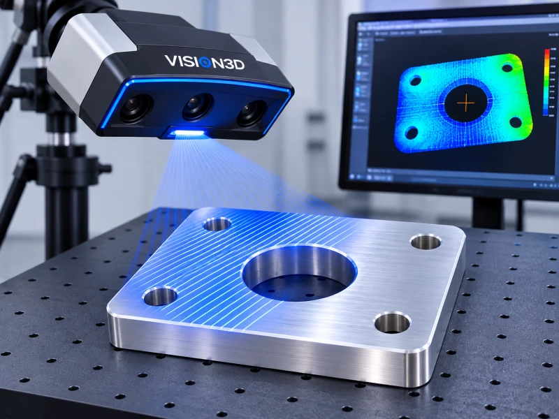
Consider a machined aluminum mounting plate with four clearance holes. The drawing specifies the location of each hole relative to three datums. During inspection, the operator needs to determine whether the manufactured hole pattern can satisfy the intended assembly relationship.
At first glance, measuring the holes may appear straightforward: scan the plate, identify four circles, and compare their centers with the CAD model. That approach can be useful for a simple two-dimensional location check, but it may not satisfy a geometric position tolerance specified on the engineering drawing.
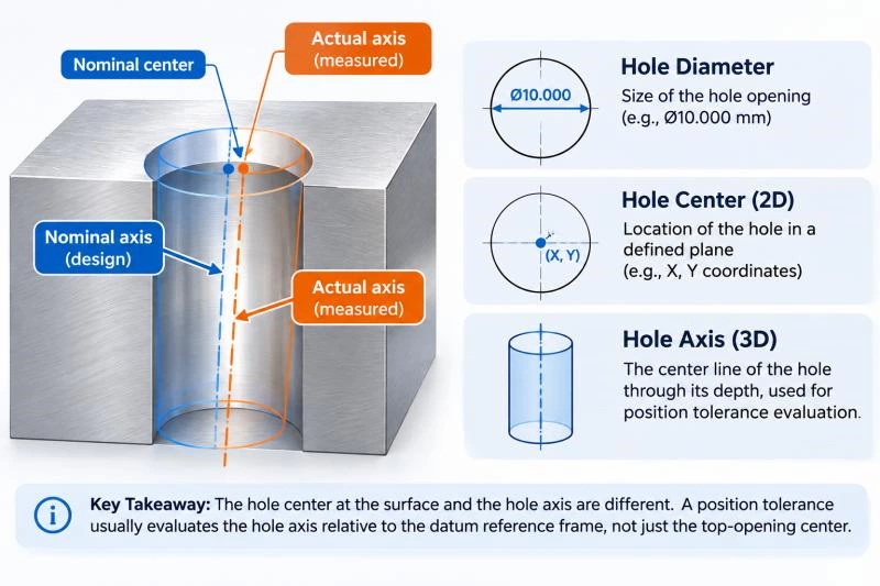
A hole has several measurable characteristics. Its diameter describes size, while its center at a particular cross-section describes a two-dimensional location. A cylindrical hole also has an axis, which describes its orientation and location through the measured depth. These characteristics are related, but they are not interchangeable.
For a through-hole controlled by a cylindrical position tolerance zone, the evaluation generally concerns the derived axis relative to the specified datum reference frame. A center measured only at the entrance may not represent that axis, especially when the bore is tilted or its shape changes along its depth.
For example, two holes can have nearly identical centers on the top surface of a plate while their axes point in different directions. A measurement based solely on the top opening might suggest that both holes are acceptable. A proper axis-based evaluation could reveal that one of them does not satisfy the drawing.
The first question should therefore be: What geometric characteristic does the drawing actually control? The answer determines which surfaces must be captured, how the feature should be constructed, and whether optical scanning alone can provide sufficient evidence.
How to Measure Hole Position with a 3D Scanner
A reliable inspection begins before the first scan. The drawing defines the measurement task; the scanner supplies geometric observations; the inspection software converts those observations into dimensional results.
The following workflow uses a machined mounting plate as an example. The same principles apply to brackets, tooling plates, cast housings, and other components with accessible mounting features.
1. Review the Drawing and Identify the Datums
Before scanning, identify the hole or hole pattern being inspected, its basic dimensions, and the datum reference frame specified by the drawing. Determine whether the requirement is a simple coordinate check, a hole-spacing dimension, or a geometric position tolerance.
Suppose the drawing establishes a primary datum from the mounting face, a secondary datum from a locating feature, and a tertiary datum that completes the coordinate system. Those datums define how the hole position must be evaluated.
The datum reference frame is not merely a convenient CAD orientation. It represents the reference conditions specified for the part. Replacing it with an unconstrained best-fit alignment can change the apparent hole deviation and may conceal a functional location error.
Also check whether the position tolerance includes a material condition modifier. A tolerance specified at maximum material condition may permit additional positional tolerance under defined size conditions. That evaluation requires suitable size measurements and the applicable drawing standard; it cannot be inferred from the hole center coordinates alone.
2. Capture the Hole and Its Surrounding Geometry
Scan the accessible mounting face and other surfaces needed to establish the datum reference frame. Then capture the hole openings and as much of the relevant internal wall as the optical geometry allows.
For shallow, accessible holes, several viewing directions may provide sufficient data for a circle or cylinder fit. For deeper bores, the opening can obstruct both the projected light and the scanner's cameras. The point cloud may contain a well-defined rim but only a narrow strip of internal wall.
Changing the scanning angle can improve coverage, provided the scanner remains within its intended working conditions and the different views can be registered reliably. Capturing the surrounding geometry first also helps maintain a consistent relationship between the hole and the rest of the component.
The objective is not to collect the maximum possible number of points. It is to collect data distributed across the geometric region needed for the measurement.
For example, a dense cluster of points on one side of a hole may be less useful for establishing its center than a smaller number of reliable points distributed around the circumference. Similarly, points concentrated near the entrance may not adequately describe the direction of a long bore.
Inspect the raw scan before accepting the feature. Missing wall regions, reflections, burrs, and edge artifacts can all influence the fitted geometry. A visually smooth mesh is not proof that the underlying measurements are complete.
3. Extract the Hole Center or Axis
After scanning, isolate the measured points belonging to the required hole feature. The appropriate fitting method depends on the characteristic being evaluated and the available data.
For a hole location defined in a particular plane, the software may calculate a circle from a suitable cross-section and report its center coordinates. When the requirement concerns a cylindrical feature, a cylinder fit may be needed to estimate the feature axis from measured wall points.
These two constructions should not be treated as equivalent. A circle fitted to an entrance edge represents a local geometric result. A cylinder fitted from sufficiently distributed wall data can provide information about the bore axis, although its reliability still depends on the observed region and the fitting procedure.
Edge extraction requires particular care. A chamfered hole, for example, may produce several circular boundaries at different diameters and heights. Selecting the chamfer edge instead of the intended cylindrical wall can shift the reported center or change the fitted diameter.
The inspection procedure should specify which points are included, how outliers are handled, and which fitting method is used. Different fitting criteria can produce different feature parameters, particularly when the manufactured hole contains form errors.
Review the fitted feature against the measured point cloud rather than accepting the software result automatically. A numerical center coordinate may look precise even when it was calculated from incomplete or poorly distributed data.
4. Establish the Datum Reference Frame
Once the relevant features have been extracted, construct the measurement coordinate system using the datums specified on the drawing.
For a typical three-datum arrangement, the primary datum constrains the appropriate degrees of freedom, followed by the secondary and tertiary datums. The exact construction depends on the datum feature types, their order of precedence, the applicable standard, and any specified material boundary conditions.
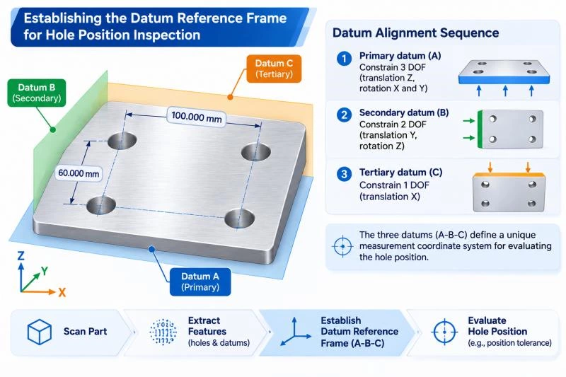
A broad mounting surface may be represented using measured plane data when the selected region is appropriate. A locating hole or slot may require its own feature construction. Where the datum itself cannot be captured reliably, a different measurement method may be necessary.
Global best-fit alignment remains useful for many surface comparison tasks, but it should not automatically replace a drawing-defined datum alignment. A best-fit procedure can distribute deviations across the part, changing the reported location of a hole relative to its functional references.
In inspection software such as VisionInspect, the important consideration is whether the required feature construction, datum alignment, and dimensional evaluation can be performed using an appropriate and verified workflow.
5. Evaluate the Hole Position
With the feature and datum reference frame established, compare the measured hole location with the nominal location defined by the engineering drawing.
For a basic coordinate inspection, the result may be expressed as deviations in X and Y. For a geometric position tolerance, the evaluation must follow the specified tolerance zone and the relevant geometric characteristic.
Do not assume that a small coordinate deviation automatically means the hole passes. A tilted bore can satisfy a center-location check at one section while failing an axis-based position requirement. Conversely, the applicable material condition rules may affect the permissible position error when those conditions are specified.
The final report should identify the measured characteristic, datum reference frame, nominal values, actual results, applicable tolerance, and conformity decision. The report should also retain enough information to reproduce the measurement procedure when required.
Calculating Hole Position Error: A Practical Example
Consider a simplified inspection of a hole center in a defined measurement plane. The part has already been aligned to its specified datum reference frame, and the nominal center coordinates are available from the drawing.
The following values are illustrative and do not represent actual measurements from a VISION3D system.
| Coordinate | Nominal Position | Measured Position | Deviation |
|---|---|---|---|
| X | 50.000 mm | 50.035 mm | +0.035 mm |
| Y | 30.000 mm | 29.975 mm | -0.025 mm |
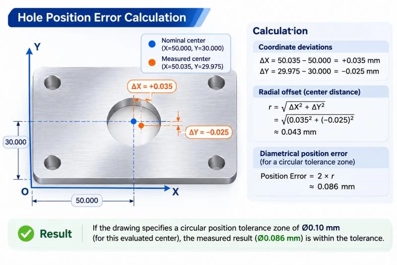
The coordinate deviations are:
ΔX = 50.035 − 50.000 = +0.035 mm
ΔY = 29.975 − 30.000 = −0.025 mm
The radial distance between the nominal and measured centers in the evaluation plane is:
r = √(ΔX² + ΔY²)
r = √(0.035² + 0.025²) ≈ 0.043 mm
For a simplified two-dimensional evaluation against a circular position tolerance zone, the corresponding diametrical position error is:
Position Error = 2 × r ≈ 0.086 mm
If the drawing specifies a circular position tolerance zone of 0.10 mm diameter for this evaluated center, and no additional material condition effects apply, the calculated center deviation falls within that simplified zone.
However, the example does not establish conformity for every possible hole position requirement. A cylindrical position tolerance applied to a bore axis requires evaluation of the derived axis within the specified three-dimensional tolerance zone. The result may also depend on the relevant datum constraints, feature size, material condition modifiers, and measurement uncertainty.
For an actual production decision, the inspection software and measurement procedure must implement the drawing's requirements rather than relying on a generic center-distance calculation.
Why Hole Geometry Can Produce Incorrect Measurements
The most difficult part of hole inspection is often not calculating a coordinate. It is determining whether the available scan data genuinely represents the feature being measured.
Several common geometric conditions can produce misleading results even when the point cloud appears clean.
Chamfers, Burrs, and Irregular Hole Entrances
A machined hole may have a chamfer, countersink, or deburred edge. These features can create several apparent circular boundaries near the entrance.
If the software selects the wrong boundary, the reported circle may not correspond to the cylindrical feature specified on the drawing. Burrs and local edge damage can also distort a fitted circle, especially when the usable circumference is limited.
For position measurement, select the geometric region that represents the controlled feature. Where the drawing requires a bore axis, the entrance edge alone may be insufficient.
Incomplete Circumferential Coverage
Imagine fitting a circle from points covering only a short arc. Multiple circles with different centers and radii may approximate that arc reasonably well, particularly when measurement noise is present.
As the angular coverage becomes more limited, the fitted center can become increasingly sensitive to small changes in point selection or filtering. A dense point cloud does not necessarily solve this problem if all the points occupy essentially the same portion of the circumference.
Review the angular distribution of the measured data and the stability of the fitted feature. Where possible, compare results from different scan directions or independent acquisitions.
Deep Holes and Unobserved Bore Axes
Deep bores create a more fundamental limitation. Optical scanners require a usable path for illumination and observation. As the bore becomes deeper relative to its opening, the surrounding walls increasingly obstruct the scanner's view.
A scan may capture the entrance and upper wall while leaving the lower portion unmeasured. Fitting a cylinder to the visible region may provide a local axis estimate, but it does not necessarily establish the geometry of the full bore.
For example, a hole may be slightly tapered, curved, or misaligned along its depth. An axis estimated from the upper few millimeters may not adequately represent the feature required by the drawing.
Multiple viewing angles can improve coverage when optical access remains possible. They cannot reveal surfaces that are physically inaccessible to the illumination and camera system.
When the Hole Axis Cannot Be Captured Directly
When the required bore geometry cannot be measured optically, a supplementary measurement method may be appropriate. Depending on the feature, tolerance, and available equipment, this may involve a coordinate measuring machine, qualified contact probing, or another suitable metrology process.
A calibrated cylindrical pin can sometimes be used to make an otherwise inaccessible hole direction observable from the outside. However, the pin's relationship to the bore must be controlled. Clearance, fit, pin straightness, seating, and tilt can introduce errors, so the external cylinder should not automatically be treated as an exact representation of the hole axis.
If optical and contact measurements are combined, the coordinate relationship between their datasets must be established and verified. Measuring the exterior with one instrument and the bore with another does not automatically produce a valid common datum reference frame.
The appropriate method is the one that can measure the required characteristic with adequate uncertainty, not necessarily the method that produces the largest amount of surface data.
How to Verify Hole Position Measurement Results
A successful feature fit is only the beginning of measurement verification. Before using the result for acceptance, engineers need evidence that the complete procedure is suitable for the required tolerance.
Start by examining data coverage. Check whether the measured points represent the intended cylindrical wall or section, whether the circumferential and axial distributions are sufficient, and whether reflections or edge artifacts have influenced the result.
Next, test the stability of feature extraction. Refit the feature using a controlled procedure and examine whether reasonable changes in data selection materially affect the calculated center or axis. Large changes suggest that the result may be sensitive to incomplete coverage, form error, or noise.
Repeatability testing should involve independent scans, not merely repeated calculations from one stored point cloud. Remove and reposition the component when that reflects the normal production workflow, then repeat acquisition, alignment, feature extraction, and evaluation.
Where the tolerance is demanding, compare the optical result with an appropriate reference measurement. A calibrated artifact or a verified measurement from another suitable instrument can help reveal systematic differences that repeated scanning alone would not detect.
| Inspection Condition | What to Check | Recommended Response |
|---|---|---|
| Shallow hole with adequate wall coverage | Point distribution and feature-fit stability | Evaluate the fitted feature using a verified procedure |
| Hole with chamfered entrance | Whether selected points represent the intended feature | Exclude unrelated edge geometry according to the inspection plan |
| Deep bore with limited wall data | Whether the required axis is observable | Use supplementary measurement when optical data is insufficient |
| Incomplete datum geometry | Validity of the datum reference frame | Revise acquisition or establish the datum using an appropriate method |
| Measured result close to the tolerance limit | Measurement uncertainty and decision rule | Apply the approved conformity assessment procedure |
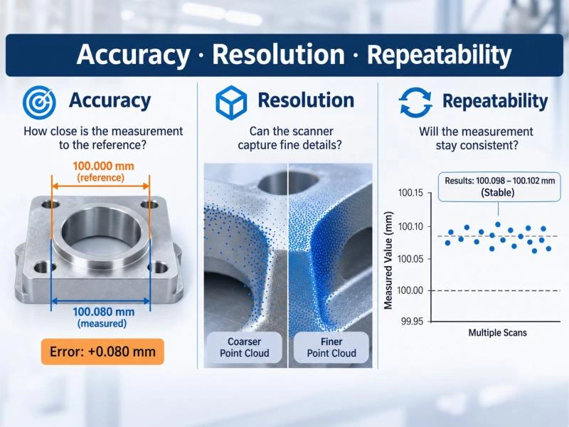
Measurement uncertainty deserves particular attention. A nominal hole position tolerance of 0.05 mm does not mean that any scanner with a published accuracy figure below 0.05 mm is automatically suitable.
The complete measurement process introduces uncertainty through calibration, scanning conditions, feature extraction, alignment, and other influences. When the uncertainty is large relative to the tolerance, a result near the limit may not support a confident pass-or-fail decision.
For recurring production inspection, the verification plan should reflect the actual operating conditions. A measurement procedure that performs well on a stable laboratory fixture may behave differently when parts are repeatedly loaded, clamped, scanned, and removed on a production line.
Hole Position Inspection in Manufacturing
Hole position inspection is particularly important where several components must locate and fasten together. A mounting hole may have an acceptable diameter and a clean machined surface but still cause assembly interference because its location or orientation is incorrect.
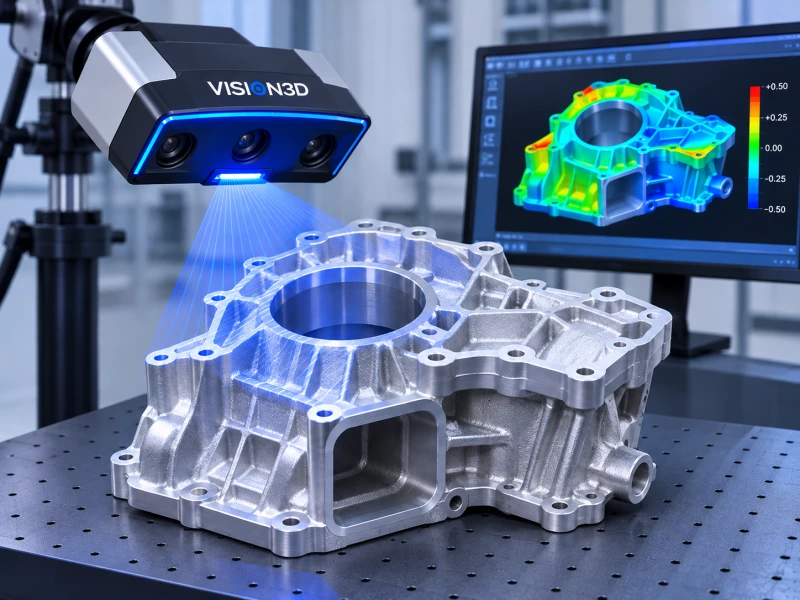
On a machined aluminum housing, multiple threaded or clearance holes may need to align with a mating cover. Optical scanning can provide useful surface and accessible feature data while also supporting inspection of the surrounding geometry. For deep threaded features, however, the required measurement characteristic may call for additional methods.
Automotive brackets and structural components introduce another challenge. Their hole patterns may span relatively large distances, and the component may deform depending on how it is supported or clamped. In these cases, the measurement setup and datum simulation can be just as important as the scanner's local feature resolution.
Tooling plates and fixtures also depend on accurately located reference holes. An error in a locating feature can influence every subsequent part positioned by the fixture. Inspection should therefore follow the functional datum structure rather than treating each hole as an isolated geometric object.
For manufacturers evaluating optical measurement equipment, the PowerScan Series provides a relevant starting point for discussing accessible part geometry and dimensional inspection requirements. The actual suitability of a system for hole position measurement must be established from the feature dimensions, optical access, required tolerance, and verified measurement performance.
For repeated inspection tasks, the workflow also needs to be practical. The time required to position the part, acquire the scan, extract features, apply datum alignment, and generate a report can determine whether a method is appropriate for routine production use.
Reliable inspection is therefore a combination of suitable measurement hardware, appropriate software, and a documented procedure that reflects the drawing and manufacturing process.
Conclusion
Measuring hole position with a 3D scanner requires more than identifying a circular opening in a point cloud. The measured data must represent the intended feature, the center or axis must be constructed appropriately, and the result must be evaluated within the correct datum reference frame.
Optical scanning can be effective for accessible holes and components that also require broader surface inspection. Deep bores, incomplete wall coverage, tight tolerances, and hidden datums may require supplementary measurement methods. The final decision should be based on verified measurement capability rather than point density or visual scan quality alone.
If your application involves mounting-hole patterns, machined housings, or complex components requiring dimensional inspection, contact the VISION3D engineering team to discuss the part geometry, tolerance requirements, and appropriate inspection workflow.
Frequently Asked Questions
Can a 3D scanner measure hole position accurately?
Yes, when the required hole geometry and datum features can be captured with sufficient quality and the complete measurement procedure has been verified for the specified tolerance. Accuracy depends on data coverage, feature construction, alignment, and measurement uncertainty rather than point density alone.
Can a 3D scanner measure the position of a deep hole?
It depends on the bore geometry and the required characteristic. An optical scanner may capture the entrance and part of the internal wall, but that does not necessarily establish the full bore axis. Contact probing or another suitable method may be required when the relevant internal geometry is not sufficiently visible.
What is the difference between hole center deviation and position tolerance?
Hole center deviation describes the difference between a measured center and its nominal location in a defined plane. A geometric position tolerance establishes an allowable zone relative to specified datums and may control an axis or another derived feature. The applicable evaluation depends on the drawing and relevant GD&T standard.
Why can two scans produce different hole center measurements?
Differences can arise from scanning angle, incomplete point coverage, surface reflections, feature selection, fitting methods, or alignment. Independent repeated scans help determine whether these variations are significant for the intended inspection.
When should a CMM or contact probe be used for hole inspection?
A suitable contact measurement method should be considered when the required bore sections or datum features cannot be observed optically, or when the measurement uncertainty of the optical procedure is insufficient for the tolerance. The choice should be based on the required characteristic, accessibility, and verified performance of the complete measurement process.