3D Scanning Software for Industrial Inspection: Features, Workflow and Selection
Industrial 3D scanning does not end when a scanner captures the surface of a part. The raw measurement data still needs to be processed, aligned, analyzed, and converted into information that engineers can use for dimensional inspection, CAD comparison, quality control, or reverse engineering. This is where 3D scanning software becomes essential.
Depending on the application, the software may control the scanner, process point clouds, generate polygon meshes, align scan data with CAD models, calculate dimensional deviations, evaluate geometric tolerances, and generate inspection reports. In automated systems, software may also coordinate scanners, robots, fixtures, rotary tables, and production equipment.
For industrial users, choosing 3D scanning software therefore involves more than checking whether it can create a 3D model. Quality engineers and manufacturers need to consider the entire measurement workflow—from data acquisition to final inspection results.
This guide explains what 3D scanning software does, how an industrial scanning workflow operates, which features are important for dimensional inspection, and what to consider when selecting software for manual or automated 3D measurement.
What Is 3D Scanning Software?
3D scanning software is the software environment used to acquire, process, manage, and analyze three-dimensional measurement data captured by a 3D scanner. It acts as the connection between the physical measurement device and the digital results used by engineers.
At a basic level, software receives data from the scanner and converts it into a digital representation of the measured object. Depending on the system, this representation may initially appear as a point cloud and later be converted into a polygon mesh or other usable 3D data format.
Industrial 3D scanning software can go much further. A metrology-oriented platform may support the complete inspection process, including:
- Scanner setup and measurement control
- Real-time scan data acquisition
- Point cloud filtering and optimization
- Multiple-scan alignment and data fusion
- Polygon mesh generation
- Alignment to CAD models
- Dimensional measurement
- Surface deviation analysis
- GD&T evaluation
- Inspection report generation
- Automated inspection workflows
The required functions depend heavily on the application. Software used to digitize a component for visualization does not need the same measurement tools as software used to determine whether an automotive part meets engineering tolerances.
Different Types of 3D Scanning Software
The term 3D scanning software covers several types of software that serve different stages of the digital measurement workflow. Some platforms combine many of these functions, while others specialize in one task.
| Software Type | Main Purpose | Typical Functions |
|---|---|---|
| Scanner Control Software | Operate the scanner and capture data | Scanner settings, exposure, scan mode, calibration status, real-time acquisition |
| Scan Processing Software | Prepare raw scan data for further use | Noise removal, point cloud filtering, alignment, fusion, mesh generation |
| Inspection & Metrology Software | Evaluate dimensional quality | CAD comparison, dimensional measurement, GD&T, deviation maps, inspection reports |
| Reverse Engineering Software | Convert physical geometry into reusable design data | Mesh editing, section extraction, surface reconstruction, preparation for CAD modeling |
For industrial inspection, software that combines data acquisition with metrology functions can reduce the number of separate programs required between scanning and final quality reporting. This becomes especially important when inspection is repeated across multiple parts or integrated into a production line.
3D Scanning Software vs 3D Modeling Software
3D scanning software and 3D modeling software both work with three-dimensional data, but their purposes are different.
3D scanning software begins with a real physical object. Its job is to capture and process measured geometry so that the digital result represents the actual condition of the part.
3D modeling software is generally used to create, modify, or design digital geometry. The geometry may be created from engineering dimensions, sketches, design features, or artistic modeling rather than direct physical measurement.
For example, scanning software may capture the actual shape of a stamped automotive panel and produce a measured surface. Inspection software can then compare that surface with the nominal CAD model to determine where the manufactured part deviates from the design.
A CAD or modeling program, by contrast, is primarily concerned with creating or modifying the nominal design itself.
The two can be used together. A reverse engineering workflow may begin with scan acquisition and point cloud processing, then transfer cleaned geometry into CAD software for surface reconstruction or design modification.
What Does 3D Scanning Software Do?
The capabilities of 3D scanning software vary from basic data capture to complete dimensional inspection. In industrial applications, the most useful platforms support several stages of the measurement workflow rather than treating scanning as an isolated step.
Scanner Control and Data Acquisition
The first responsibility of scanning software is to establish communication between the measurement device and the operator. Depending on the scanner, software may provide controls for measurement mode, exposure, acquisition range, calibration status, scanning parameters, and real-time data display.
During scanning, the operator needs immediate feedback about whether sufficient data is being captured. Missing areas, unstable tracking, incorrect exposure, or insufficient overlap between scan positions may reduce the quality of the final dataset.
Real-time visualization allows the operator to identify these issues before the inspection is completed, reducing the need to repeat the entire measurement later.
In automated systems, data acquisition may be triggered by a programmed sequence rather than manually by an operator. Software can coordinate when the scanner captures data and how each measurement position is incorporated into the inspection workflow.
Point Cloud Processing
Many 3D measurement systems initially generate a point cloud consisting of large numbers of measured XYZ coordinates representing the surface of the object.
Raw point cloud data usually requires processing before it can be used efficiently for inspection or reverse engineering. Common processing operations include:
- Removing isolated or invalid points
- Filtering measurement noise
- Combining data captured from multiple positions
- Reducing unnecessary data density
- Correcting overlapping scan regions
- Preparing the dataset for meshing or inspection
The objective is not simply to create the densest possible point cloud. Industrial inspection requires data that accurately represents the measured surface while remaining stable and manageable for downstream analysis.
Mesh Generation and Surface Reconstruction
After point cloud processing, many workflows convert the measurement data into a polygon mesh. The software connects neighboring measurement points to create a continuous digital surface, commonly represented by triangular elements.
A mesh is useful because it provides a more intuitive representation of the complete part geometry and can be used for:
- Full-surface visualization
- Scan-to-CAD comparison
- Surface deviation analysis
- Reverse engineering preparation
- Archiving the measured condition of a part
Mesh generation should preserve important geometric features without introducing excessive smoothing. Aggressive processing may make a model look cleaner visually while removing small dimensional features or local deviations that are important for inspection.
For metrology applications, data processing should therefore prioritize measurement integrity rather than appearance alone.
Scan Alignment
Industrial parts are rarely captured from a single scanner position. Complex geometry, hidden surfaces, and large components often require multiple scans that must be combined into one consistent coordinate system.
3D scanning software performs this alignment using geometric features, reference targets, datums, or CAD geometry. The alignment method matters because it determines how the measured part is positioned before dimensional analysis begins.
Common alignment approaches include:
- Feature-based alignment — uses recognizable geometric features or surface characteristics to combine scan data.
- Reference target alignment — uses coded or optical targets to establish relationships between different scanner positions.
- Best-fit alignment — mathematically minimizes the overall deviation between measured data and nominal geometry.
- Datum alignment — positions scan data according to engineering datums defined on the drawing or CAD model.
Choosing the correct method is especially important in dimensional inspection. Best-fit alignment may be useful for understanding overall shape variation, while datum-based alignment is often more appropriate when the inspection must reflect how a part is located or assembled in production.
CAD Comparison
CAD comparison is one of the most important functions of industrial 3D scanning software. Instead of checking only a few individual dimensions, engineers can compare the measured surface of the entire part with its nominal CAD geometry.
The typical process is:
Scan Data → Alignment → CAD Comparison → Deviation Analysis
Once the measured data has been aligned with the CAD model, the software calculates the distance between the actual surface and the nominal design at thousands or millions of locations.
This makes it possible to identify:
- Surface deformation
- Warpage
- Springback
- Local dimensional variation
- Assembly distortion
- Tooling-related deviations
- Areas that exceed tolerance limits
For complex freeform parts such as automotive panels, castings, molds, aerospace components, or battery structures, full-field CAD comparison can reveal geometric behavior that would be difficult to understand from a small number of manually measured points.
Dimensional Measurement
In addition to full-surface comparison, 3D scanning software can extract conventional dimensional measurements from the captured data.
Depending on the software and inspection setup, engineers may evaluate:
- Length and distance
- Diameter
- Radius
- Angle
- Hole position
- Feature spacing
- Cross-sectional dimensions
- Surface relationships
The advantage is that these measurements can often be created after the part has already been scanned. Engineers can return to the stored dataset and evaluate additional features without necessarily measuring the physical component again, provided the captured data contains the required geometry and measurement quality.
This can be useful during design review, supplier quality analysis, and troubleshooting when new dimensional questions arise after the original inspection.
GD&T Inspection
For engineering inspection, individual dimensions are often not enough. Parts may also need to meet geometric dimensioning and tolerancing requirements defined on technical drawings.
Metrology-oriented 3D scanning software may provide tools for evaluating geometric characteristics such as:
- Flatness
- Profile of a surface
- Position
- Parallelism
- Perpendicularity
- Cylindricity
The suitability of 3D scanning for a particular GD&T characteristic depends on the feature geometry, accessibility, tolerance, scanner capability, alignment method, and inspection procedure.
Full-field scanning is particularly useful for geometric characteristics involving surfaces and overall form because the software can analyze a much larger portion of the component than a small number of discrete measurement points.
However, very tight tolerances, deep internal features, or geometries that cannot be captured reliably by the optical system may still require complementary measurement methods. The inspection strategy should therefore be based on the actual tolerance and feature rather than assuming one measurement technology is suitable for every requirement.
Color Deviation Maps
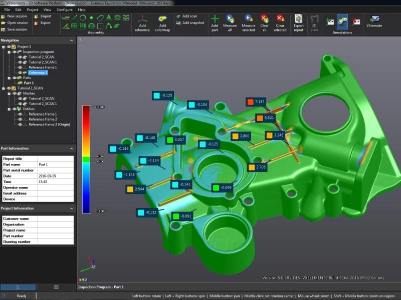
A color deviation map converts numerical CAD comparison results into an intuitive visual representation. Instead of reviewing thousands of individual deviation values, engineers can quickly identify where a manufactured surface differs from the nominal design.
A typical deviation map uses a color scale to represent different ranges of dimensional variation. For example, one color range may indicate material or geometry above the nominal surface, another may indicate negative deviation, and a central range may represent areas close to the design condition.
The exact color settings should always be interpreted according to the tolerance scale configured in the inspection software. A red area does not automatically mean a part has failed; it only represents the deviation range assigned to that color.
Deviation maps are useful for:
- Visualizing warpage across large surfaces
- Evaluating stamped or formed components
- Checking casting deformation
- Analyzing tooling changes
- Comparing pre-process and post-process geometry
- Communicating inspection results to engineering teams
Because the result is visual, a color map can also make it easier for manufacturing, quality, and tooling teams to discuss the same dimensional problem without relying only on tables of measurement values.
Inspection Reporting
Measurement results become more useful when they can be organized into a consistent inspection report. Industrial 3D scanning software may combine numerical dimensions, GD&T results, deviation maps, annotations, screenshots, and pass/fail information into a structured report.
Reporting functions can help standardize communication between:
- Quality departments
- Manufacturing engineers
- Tooling teams
- Suppliers
- Customers
- Production management
For repeated inspection, report templates can also reduce manual work. The same measurement characteristics, tolerance settings, views, and report structure can be reused across multiple parts when the inspection process is standardized.
In automated production environments, reporting may be integrated into the inspection sequence so that measurement results are generated automatically after each completed scan cycle.
Typical 3D Scanning Software Workflow
Although software platforms differ, most industrial workflows follow a similar path from physical measurement to engineering decision. Understanding this sequence helps users evaluate whether a software package supports the complete inspection process or only one part of it.
Scan → Process → Align → Compare → Measure → Report
1. Scan the Part
The scanner captures the physical geometry of the component. Software controls the acquisition process and provides feedback about data coverage, tracking, exposure, or measurement status.
2. Process the Measurement Data
Raw data is cleaned and prepared for analysis. This may include removing invalid points, filtering noise, combining multiple scans, and generating a usable point cloud or polygon mesh.
3. Align the Data
The measured geometry is placed into the required coordinate system. Depending on the inspection task, this may use reference targets, geometric features, engineering datums, or best-fit alignment.
4. Compare with Nominal Geometry
If CAD data is available, the software compares the measured part with the nominal model and calculates surface deviations throughout the inspected area.
5. Perform Dimensional Inspection
Engineers can evaluate dimensions, geometric tolerances, cross-sections, feature positions, or other quality characteristics required by the drawing or inspection plan.
6. Generate the Inspection Result
The final stage converts the analysis into information that can be used for engineering decisions. This may include color maps, dimensional tables, GD&T results, pass/fail judgments, screenshots, and inspection reports.
A well-integrated workflow reduces unnecessary data transfer between separate software packages and makes repeated inspection easier to standardize, particularly when the same parts are measured throughout production.
How 3D Scanning Software Supports Industrial Inspection
The value of 3D scanning software becomes clearer when its functions are applied to real manufacturing tasks. Different inspection stages may use the same scan data in different ways, from validating a first production part to monitoring repeated manufacturing output.
First Article Inspection
During first article inspection, 3D scanning software can compare an initial manufactured component with its CAD model before full production begins.
Instead of checking only selected dimensions, engineers can examine the complete accessible surface for unexpected deformation or dimensional variation. Additional dimensional and GD&T characteristics can then be evaluated according to the inspection plan.
This helps manufacturing teams identify issues related to tooling, forming, machining, casting, or assembly before they affect a larger production batch.
Production Quality Control
Once production is stable, the same inspection workflow can be reused for repeated parts. Software templates can preserve alignment rules, inspection characteristics, tolerance limits, and reporting requirements.
This can reduce the amount of manual setup required for each inspection and make results easier to compare over time.
For high-volume applications, changes in surface deviation or dimensional trends may also help engineers identify process drift before parts move significantly outside the required tolerance range.
Reverse Engineering
3D scanning software also plays an important role when no usable CAD model exists. Scan data can be cleaned, aligned, meshed, and prepared for downstream reverse engineering.
Depending on the application, engineers may extract sections, reference features, or surface information from the scanned geometry before rebuilding the component in CAD.
This workflow is commonly used for legacy parts, tooling reconstruction, design modification, and components for which original design data is incomplete or unavailable.
Automated Inspection
In an automated inspection system, software performs a broader role than data processing alone. It may coordinate the scanner with robots, fixtures, rotary tables, PLCs, or other production equipment.
An automated sequence can include:
- Loading or positioning the part
- Moving the scanner to predefined measurement positions
- Capturing scan data automatically
- Processing and aligning the dataset
- Running predefined inspection characteristics
- Generating pass/fail results
- Creating or storing the inspection report
This type of workflow is particularly useful when the same component must be measured repeatedly and inspection consistency is more important than operator flexibility.
Solutions such as the AutoScan Series combine automated measurement hardware with software-driven inspection workflows for production-oriented dimensional quality control.
3D Scanning Software vs 3D Inspection Software
The terms 3D scanning software, 3D inspection software, and 3D metrology software are often used together, but they do not always describe the same level of functionality.
3D scanning software is generally focused on acquiring and processing data from a scanner. Inspection software goes further by turning that data into measurable quality information. Metrology software usually combines measurement, tolerance evaluation, reporting, and more advanced inspection functions within a broader dimensional-control workflow.
| Software Type | Main Purpose | Typical Functions |
|---|---|---|
| 3D Scanning Software | Capture and process 3D measurement data | Scanner control, point clouds, alignment, fusion, mesh generation |
| 3D Inspection Software | Evaluate manufactured parts against requirements | CAD comparison, dimensional measurement, deviation maps, tolerance checks |
| 3D Metrology Software | Support comprehensive dimensional measurement | Measurement planning, GD&T, feature fitting, reporting, traceable inspection workflows |
| Reverse Engineering Software | Convert measured geometry into design data | Mesh repair, section extraction, surface reconstruction, CAD preparation |
In practice, these categories increasingly overlap. An industrial software platform may control the scanner, process point clouds, compare data with CAD, calculate geometric characteristics, and generate reports without requiring the operator to move between several separate applications.
The important question is therefore not only what the software is called, but whether it supports the complete workflow required by the application.
Manual vs Automated 3D Inspection Software
The software requirements for a manually operated 3D scanner can be very different from those of an automated inspection cell. Both may use similar measurement and analysis tools, but automation introduces additional requirements for equipment coordination, repeatability, process control, and unattended operation.
Software for Manual 3D Inspection
In a manual inspection workflow, an operator controls the scanner and decides how the part should be captured. The software provides feedback during measurement and then supports processing, alignment, inspection, and reporting.
A typical manual workflow may include:
- Selecting the appropriate scan mode
- Adjusting measurement settings
- Monitoring scan coverage
- Aligning multiple scan positions
- Comparing the result with CAD
- Creating dimensional inspection results
- Generating the final report
Manual workflows are suitable when parts change frequently, measurement locations vary, or inspection requires flexible operator decisions.
They are commonly used for prototype inspection, low-volume production, reverse engineering, tooling analysis, supplier inspection, and on-site measurement.
Software for Automated 3D Inspection
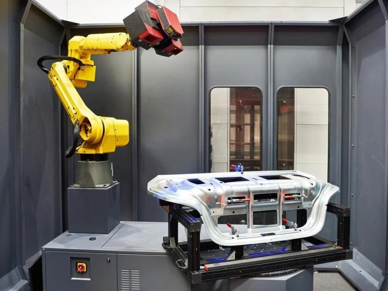
Automated inspection software must support more than measurement analysis. It also needs to coordinate the sequence in which scanners and other equipment operate.
Depending on the inspection cell, software may communicate with:
- Industrial robots
- Rotary tables
- Positioning systems
- Fixtures
- PLCs
- Production line controls
- Data management systems
The objective is to convert an inspection plan into a repeatable production process. Once the part enters the measurement station, the system can follow predefined scanner positions, capture the required data, perform analysis, and output the result with minimal operator intervention.
A typical automated workflow can be represented as:
Part Positioning → Automatic Scanning → Data Processing → Inspection → Pass/Fail → Report
For repeated production inspection, automation can improve consistency because scan positions, measurement parameters, alignment strategies, tolerance settings, and report formats can all be standardized.
However, automated inspection software must also account for system-level factors. A high-accuracy scanner alone does not guarantee repeatable automated measurement if the robot, fixture, coordinate relationship, or part-loading process is unstable.
Why Automation Changes Software Requirements
Manual inspection depends heavily on operator decisions. Automated inspection replaces many of these decisions with predefined logic, which increases the importance of software configuration and system integration.
For example, automated software may need to determine:
- Which measurement program should run for a particular part
- Where the scanner should be positioned
- Whether sufficient data has been captured
- How scan data should be aligned
- Which inspection characteristics should be calculated
- Whether the part passes or fails
- Where inspection results should be stored or transmitted
For manufacturers planning inline or near-line inspection, these functions can be as important as the measurement tools themselves.
What Features Should Industrial 3D Scanning Software Have?
Choosing software based only on whether it can connect to a scanner is rarely sufficient for industrial measurement. The software should support the complete path from data acquisition to the final engineering result.
The most important features depend on the application, but several capabilities are especially relevant for dimensional inspection.
| Feature | Why It Matters |
|---|---|
| Scanner Compatibility | Ensures the software can communicate with the required measurement hardware and access the necessary scanner functions. |
| Real-Time Data Acquisition | Allows operators to monitor scan coverage and identify missing or unstable data during measurement. |
| Point Cloud Processing | Provides tools for filtering, cleaning, combining, and preparing raw measurement data. |
| Alignment Tools | Supports correct positioning of scan data using features, targets, datums, or CAD geometry. |
| CAD Import and Comparison | Enables comparison between the manufactured part and nominal engineering geometry. |
| Dimensional Measurement | Allows engineers to evaluate distances, diameters, angles, positions, sections, and other measurable features. |
| GD&T Evaluation | Supports inspection of geometric characteristics defined by engineering drawings. |
| Deviation Analysis | Helps visualize full-field dimensional variation using color maps and numerical results. |
| Inspection Templates | Makes repeated inspection easier by reusing measurement characteristics, alignments, tolerances, and report settings. |
| Automated Reporting | Reduces manual report preparation and helps standardize communication of inspection results. |
| Robot and PLC Integration | Supports automated inspection cells and production-line measurement workflows. |
| Data Export | Allows measurement results or geometry to be transferred to downstream engineering and quality systems. |
Scanner Compatibility
Software compatibility should be evaluated at the beginning of the selection process. Some platforms are designed around a specific scanner family, while others may support multiple measurement devices.
The important point is not simply whether the scanner can connect, but whether the software can access the measurement functions required for the intended workflow.
For example, a basic connection may be sufficient for scan acquisition, while automated inspection may require deeper integration with measurement programs, system calibration, robot positioning, and inspection templates.
CAD Import and Inspection Tools
For dimensional quality control, CAD comparison capability is often essential. Software should allow nominal geometry to be imported and aligned with the measured part using a method appropriate for the engineering requirement.
Once aligned, the software should make it possible to evaluate both full-surface deviation and specific measurement characteristics.
This combination is important because a color map may reveal where deformation occurs, while individual dimensional or GD&T results determine whether critical features meet drawing requirements.
Reusable Inspection Templates
When the same part is measured repeatedly, rebuilding the inspection setup every time increases operator effort and introduces unnecessary variation.
Reusable templates can preserve elements such as:
- Alignment strategy
- Measurement characteristics
- GD&T definitions
- Tolerance limits
- Deviation color scales
- Report views
Once configured, the template can be applied to subsequent measurements of the same part or product family, helping standardize production inspection.
Reporting and Data Management
Inspection software should not treat reporting as an afterthought. The final result often needs to be reviewed by people who did not operate the scanner, including production engineers, quality managers, suppliers, and customers.
Clear reports should make it possible to understand:
- What was measured
- Which tolerances were applied
- Where dimensional deviations occurred
- Which features passed or failed
- When the inspection was performed
For repeated production inspection, structured data storage is also valuable because it allows results to be compared over time and may help identify gradual process changes.
How to Choose 3D Scanning Software
The right 3D scanning software depends on what needs to be measured, how the inspection will be performed, and what information must be produced at the end of the process. A software package that works well for reverse engineering may not provide the dimensional analysis, GD&T, reporting, or automation functions required for production quality control.
Before comparing individual features, manufacturers should first define the complete measurement workflow.
What Type of Parts Will You Measure?
Part size, geometry, surface complexity, and production volume all influence software requirements.
For example, a small machined component may require detailed dimensional and GD&T analysis, while a large automotive panel may depend more heavily on full-surface deviation maps, section analysis, and efficient processing of large datasets.
Typical considerations include:
- Part size and measurement volume
- Geometric complexity
- Number of features to inspect
- Required tolerance
- Surface accessibility
- Inspection frequency
- Amount of scan data generated
The software should be able to handle the expected dataset efficiently without making the inspection workflow unnecessarily complicated.
Is the Main Goal Inspection or Reverse Engineering?
Inspection and reverse engineering both begin with scanned geometry, but their downstream requirements are different.
For industrial inspection, important functions may include:
- CAD alignment
- Dimensional measurement
- GD&T evaluation
- Surface deviation maps
- Tolerance analysis
- Inspection reporting
For reverse engineering, the focus may shift toward:
- Mesh repair
- Hole filling
- Section extraction
- Curve generation
- Surface reconstruction
- Transfer to CAD modeling software
Some industrial platforms support both workflows, but the software should be evaluated according to the task that matters most to the organization.
Do You Need CAD Comparison?
If parts are manufactured from an existing design, scan-to-CAD comparison is often one of the most important software functions.
The software should not only import the nominal model but also provide suitable alignment methods and tools for interpreting the resulting deviations.
For example, quality engineers may need to determine whether a surface difference comes from:
- Part deformation
- Incorrect alignment
- Tooling variation
- Assembly distortion
- Material springback
Software that provides both numerical deviation values and full-field visualization can make these differences easier to investigate.
Do You Need GD&T Inspection?
When inspection requirements are defined by engineering drawings, basic distance measurement may not be enough. The software may also need to evaluate geometric characteristics and establish the correct datum reference system.
Before selecting software, confirm whether it supports the specific GD&T characteristics required by your inspection plan rather than assuming that all metrology platforms provide identical capabilities.
The measurement method should also be suitable for the feature itself. Some internal or highly constrained features may require complementary tactile measurement even when most of the component is inspected optically.
Will Inspection Be Manual or Automated?
A manual inspection station and an automated production cell have very different software requirements.
For manual measurement, priorities may include:
- Simple scanner control
- Fast data processing
- Flexible alignment
- Interactive measurement tools
- Easy report generation
For automated inspection, additional requirements may include:
- Robot integration
- PLC communication
- Programmed measurement sequences
- Automatic part recognition
- Reusable inspection templates
- Automatic pass/fail evaluation
- Automatic report generation
If automation is likely to be introduced later, manufacturers should consider whether the software can support that future workflow before investing in a platform designed only for manual scanning.
What Data Exchange Is Required?
3D scan data rarely remains inside one software platform for the entire product lifecycle. Geometry, inspection results, or reports may need to move into CAD, engineering, quality, or production systems.
Before selection, users should confirm which input and output formats are required by their existing workflow.
Important questions include:
- Can the software import the required CAD data?
- Can processed scan data be exported for reverse engineering?
- Can inspection results be shared with customers or suppliers?
- Can reports be generated in the required format?
- Can measurement data be connected to downstream quality systems?
Format compatibility should be verified using the actual software configuration rather than assumed from general product descriptions.
How Repeatable Is the Inspection Workflow?
For occasional measurement, operators may manually configure each inspection. In production, however, repeatability becomes increasingly important.
Software that supports reusable inspection programs can help standardize:
Alignment → Measurement Features → Tolerances → Analysis → Report
This reduces the number of decisions that must be repeated for every part and can make measurement results more consistent between inspection cycles.
How Software Affects 3D Measurement Accuracy
Measurement accuracy is determined primarily by the capability of the scanner, calibration condition, environment, measurement volume, part surface, and inspection method. Software cannot transform a measurement system beyond the physical accuracy of its hardware.
However, software still plays an important role in determining how captured data is processed and interpreted.
Several software operations can influence the final measurement result.
Calibration Data and Measurement Correction
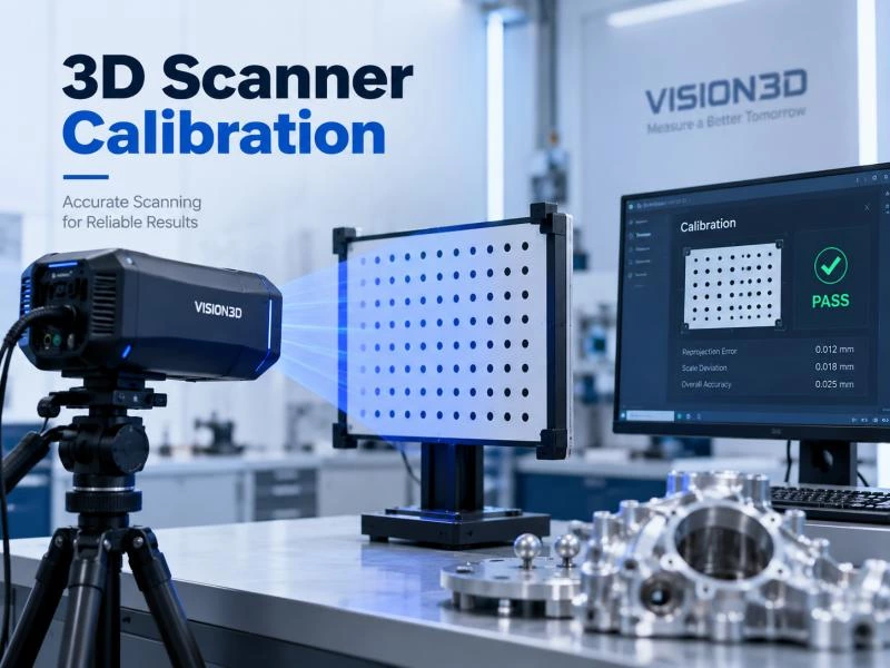
The scanner relies on calibration parameters to convert optical observations into dimensional coordinates. Software applies these parameters during data acquisition and reconstruction.
If the system is not correctly calibrated, later processing cannot reliably remove the underlying measurement error. Calibration and verification should therefore be completed before critical dimensional inspection.
For a deeper explanation of this process, see the VISION3D guide to 3D scanner calibration.
Data Filtering
Filtering can remove isolated points and measurement noise, improving the usability of a dataset. However, excessive filtering or smoothing can also alter small geometric details.
For dimensional inspection, the objective should be to remove unreliable data without artificially changing the measured surface.
Alignment Strategy
The same scan dataset can produce different deviation patterns depending on how it is aligned with the CAD model.
For example, best-fit alignment minimizes overall deviation between two geometries, while datum alignment follows defined engineering references. Neither method is automatically correct for every application.
The alignment strategy should reflect the inspection objective and the way the part is located or used in the actual assembly.
Feature Fitting
When software calculates a plane, cylinder, circle, sphere, or other geometric feature from scan data, it uses mathematical fitting methods to determine the representative geometry.
The selected data area, fitting method, and quality of the underlying scan can all influence the calculated result.
This is particularly important for dimensional inspection because the measurement displayed by the software is not simply a visual reading; it is the result of applying a defined mathematical operation to measured data.
GD&T Calculation
Geometric tolerance evaluation requires the software to interpret measured geometry according to defined datum structures and calculation methods.
For critical inspection, users should understand which standard, algorithm, and software configuration are being applied rather than treating every GD&T result as interchangeable across different platforms.
Common Mistakes When Selecting 3D Scanning Software
Software selection problems often become visible only after the scanner has already been introduced into production. Evaluating the entire measurement workflow in advance can prevent a system from becoming limited by missing inspection, automation, or reporting capabilities.
Mistake 1: Choosing Software Only Because It Connects to the Scanner
Hardware compatibility is essential, but it is only the beginning. A software package may successfully acquire scan data while lacking the tools required for dimensional inspection, GD&T, production reporting, or automated measurement.
The selection should therefore begin with the final inspection requirement rather than the scanner connection alone.
Mistake 2: Focusing Only on Point Cloud or Mesh Quality
A visually smooth 3D model does not automatically indicate that the software is suitable for industrial metrology.
For quality control, users also need to consider whether the platform can preserve measurement integrity, establish appropriate coordinate systems, perform dimensional analysis, and generate traceable inspection results.
Mistake 3: Ignoring Alignment Requirements
Alignment can strongly affect the interpretation of dimensional deviations. Software that provides only limited alignment options may not be suitable for engineering inspection based on defined datums or assembly conditions.
Before purchasing software, users should determine how their parts need to be aligned and whether those methods are supported.
Mistake 4: Underestimating Automation Requirements
A workflow that works efficiently for one manually inspected part may become impractical when hundreds of parts need to be measured repeatedly.
If production inspection is a future objective, manufacturers should evaluate whether the software can support measurement programs, robotic equipment, PLC communication, automated analysis, and repeatable reporting.
Mistake 5: Treating Reporting as a Secondary Feature
The final inspection report is often the information that engineering teams, suppliers, customers, and quality managers actually use.
If creating reports requires significant manual editing after every scan, the software may become a bottleneck even when measurement itself is fast.
For repeated inspection, reusable report templates and automatic result generation can be important parts of the overall productivity calculation.
Mistake 6: Selecting Software Without Testing the Real Workflow
Feature lists cannot always show how efficiently software will handle a specific part or inspection task.
Before deployment, it is useful to test the software with representative components and actual inspection requirements. A practical evaluation should include:
- Real scanner data
- Typical CAD files
- Required alignment methods
- Critical dimensions and tolerances
- Expected GD&T characteristics
- Report requirements
- Automation needs, if applicable
Testing the complete workflow makes it easier to determine whether the software can support production requirements rather than simply demonstrating individual features.
VisionInspect for Industrial 3D Metrology and Inspection
For industrial users, 3D scanning software is most valuable when data acquisition, processing, dimensional analysis, and inspection can be managed within a connected workflow. Reducing unnecessary transfers between separate software platforms can simplify operation and make repeated measurement easier to standardize.
VisionInspect is VISION3D's 3D metrology and inspection software platform. It is designed to work with VISION3D measurement systems and supports workflows ranging from scan data acquisition and processing to dimensional inspection and automated measurement.
Integrated Data Acquisition and Processing
VisionInspect connects measurement hardware with the software environment used to process captured data. Depending on the configured measurement system, the workflow can include data acquisition, point cloud processing, denoising, data fusion, and mesh generation.
This allows measurement data to move from scanning into downstream inspection without requiring engineers to rebuild the dataset at each stage.
The software can be used with measurement systems such as the PowerScan Series for metrology-grade optical inspection and the VScan M Series for flexible handheld measurement.
From Scan Data to Measurement Results
For dimensional inspection, the objective is not simply to produce a complete 3D model. Engineers need to convert captured geometry into information that can support quality decisions.
A typical software-driven inspection workflow can follow:
Data Acquisition → Data Processing → Alignment → Measurement Analysis → Inspection Result
Depending on the inspection task, engineers can use measured data to evaluate geometric differences, analyze manufactured components, and prepare results for downstream quality review.
This makes the software an important link between the physical scanner and the final engineering decision.
Supporting Automated Measurement Workflows
Software becomes even more important when 3D inspection is automated. In addition to processing measurement data, the platform may need to coordinate different pieces of equipment within the inspection cell.
VISION3D automated measurement solutions can combine scanners with robots, positioning devices, rotary tables, fixtures, and production-control equipment. Software coordination helps these components operate as one inspection workflow rather than as separate devices.
For production environments, the AutoScan Series can be used where repeated dimensional inspection needs to be integrated with automated scanning and standardized measurement procedures.
The appropriate configuration depends on factors such as part geometry, inspection cycle, required tolerance, production volume, and automation architecture.
Frequently Asked Questions About 3D Scanning Software
What software is used for 3D scanning?
3D scanning software varies according to the scanner and application. Basic software may focus on scanner control, point cloud capture, alignment, and mesh generation, while industrial metrology software can add CAD comparison, dimensional measurement, GD&T evaluation, deviation analysis, reporting, and automation functions.
Do all 3D scanners require software?
Yes, a digital workflow requires software to receive and process measurement data from the scanner. The level of software functionality varies significantly. Some systems use software mainly for data acquisition, while industrial scanners may rely on more comprehensive platforms for measurement analysis and quality inspection.
What is the difference between 3D scanning software and CAD software?
3D scanning software begins with measured data captured from a physical object. It is used to acquire, process, align, and analyze that geometry. CAD software is primarily used to create or modify nominal design geometry.
The two are often used together. For example, a scanned part can be processed in scanning software and then compared with a CAD model for inspection or transferred into a CAD environment for reverse engineering.
Can 3D scanning software compare scan data with CAD?
Industrial 3D scanning and inspection software can support scan-to-CAD comparison when the required functions are available. The measured geometry is aligned with the nominal CAD model, after which the software calculates dimensional differences across the inspected surface.
The results can be presented numerically or through color deviation maps, making it easier to identify deformation, warpage, local variation, and other geometric differences.
Can 3D scanning software perform GD&T inspection?
Metrology-oriented software may support GD&T evaluation for geometric characteristics such as flatness, position, profile, parallelism, or perpendicularity. The actual capability depends on the software, scanner, feature geometry, tolerance requirement, measurement strategy, and applicable inspection standard.
Users should confirm that the required characteristics and evaluation methods are supported before selecting software for production inspection.
What software is needed for automated 3D inspection?
Automated 3D inspection requires more than basic scan-processing software. The software may need to control measurement programs, coordinate scanners and robots, communicate with PLCs or positioning equipment, process scan data automatically, run predefined inspections, and generate results without continuous operator intervention.
For this reason, software compatibility with the complete automation architecture should be evaluated together with scanner performance.
Conclusion
3D scanning software is the link between captured surface data and usable engineering information. For industrial inspection, its role can extend far beyond point cloud generation to include alignment, CAD comparison, dimensional measurement, GD&T evaluation, deviation analysis, reporting, and automated measurement control.
The right software should therefore be selected according to the complete measurement workflow rather than a single feature. Part geometry, inspection requirements, tolerance, CAD comparison, reporting, automation, data exchange, and future production needs should all be considered.
For occasional manual scanning, flexible acquisition and processing tools may be sufficient. For dimensional quality control or repeated production inspection, a more integrated metrology platform can help standardize the process from data acquisition through final inspection results.
Ultimately, effective 3D scanning software should help engineers move efficiently from physical part → measurement data → dimensional analysis → engineering decision.