CMM vs 3D Scanner: Which Is Better for Dimensional Inspection?
Choosing between a Coordinate Measuring Machine (CMM) and a 3D scanner depends on what needs to be measured, how much data is required, and how the inspection results will be used. Both technologies are widely used for dimensional inspection, but they solve measurement problems in different ways.
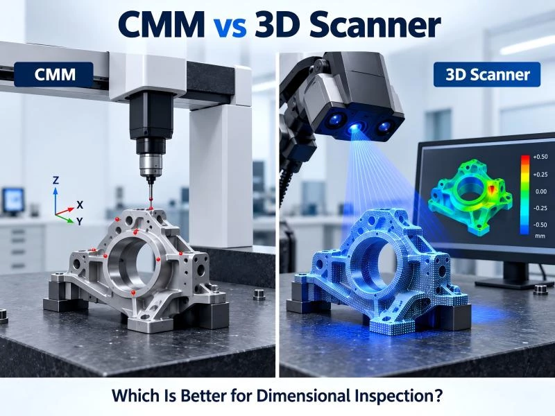
A CMM typically measures selected points and geometric features using a tactile probe within a defined coordinate system. It is well suited to critical dimensions, precise datum relationships, and features that require highly controlled point-based measurement.
A metrology-grade 3D scanner uses non-contact optical measurement to capture dense surface data across the visible geometry of a component. Instead of evaluating only predefined points, it can create a complete digital representation for CAD comparison, surface deviation analysis, and complex geometry inspection.
Neither technology is universally better. A CMM may be the stronger choice for a small number of critical features with very tight tolerances, while 3D scanning can be more efficient when manufacturers need full-surface coverage, complex freeform measurement, large-part inspection, or rapid geometric analysis.
This guide compares CMM vs 3D scanner performance across accuracy, measurement speed, data coverage, GD&T inspection, complex surfaces, large components, portability, and automation to help manufacturers choose the right dimensional inspection method.
What Is a CMM?
A Coordinate Measuring Machine (CMM) is a precision measurement system used to determine the three-dimensional position of points on a physical component. Most conventional CMMs use a tactile probe that contacts selected features while the machine records their X, Y, and Z coordinates.
These measured coordinates can be used to evaluate dimensions and geometric characteristics such as:
- Hole diameter and position
- Distances between features
- Planes and datums
- Cylindrical features
- Geometric tolerances
- Critical dimensional relationships
Fixed bridge CMMs are commonly installed in controlled metrology environments and provide a highly repeatable measurement platform for precision components. Portable CMM technologies are also available for applications that require more flexibility, so CMM should not always be treated as a completely fixed measurement method.
The main characteristic of CMM inspection is that measurement is typically based on defined points and features. Engineers program or select the locations that need to be checked, and the probe measures those specific areas according to the inspection plan.
This makes CMMs particularly effective when a component has a limited number of critical characteristics that require precise tactile measurement. However, when a part contains complex freeform surfaces or hundreds of features, collecting sufficient data point by point can require more programming and measurement time.
What Is a Metrology 3D Scanner?
A metrology 3D scanner is a non-contact measurement system that captures the visible surface geometry of a physical component and converts it into dense 3D measurement data. Depending on the system, laser or structured-light technology may be used to record the shape of the part from multiple viewpoints.
Instead of measuring only selected points, a 3D scanner can capture thousands or millions of surface points across the component. This creates a detailed digital representation that can be used for dimensional inspection, CAD comparison, deviation analysis, and quality control.
Typical measurement outputs include:
- Dense point cloud or polygon data
- Full-surface geometry
- 3D color deviation maps
- Feature dimensions and positions
- Surface profile and deformation analysis
This full-field measurement approach is especially useful for complex freeform surfaces, large components, castings, sheet metal parts, molded parts, and other geometries where a small number of discrete measurement points may not fully describe the actual part condition.
Portable metrology-grade 3D scanners also allow inspection to be performed directly on the shop floor, around large components, or at supplier and production sites. This flexibility can reduce the need to move oversized parts into a dedicated measurement room.
CMM vs 3D Scanner: Key Differences
The main difference between a CMM and a 3D scanner is not simply accuracy. The two technologies collect different types of measurement information and are therefore suited to different inspection tasks.
| Comparison | CMM | 3D Scanner |
|---|---|---|
| Measurement Method | Typically tactile, point-based measurement | Non-contact optical, full-field measurement |
| Data Density | Selected points and programmed features | Dense surface data across visible geometry |
| Best Use | Critical dimensions and precise geometric features | Complex surfaces, full-part inspection and CAD comparison |
| Freeform Surfaces | Possible, but may require more measurement effort | Well suited to dense freeform surface capture |
| Internal Features | Can measure accessible bores and internal geometry with suitable probes | Limited by optical line of sight |
| Large-Part Measurement | Depends on machine volume and CMM type | Portable systems provide greater flexibility around large parts |
| Deviation Visualization | Primarily feature-based numerical results | Strong support for full-field color deviation maps |
| Portability | Fixed systems are less portable; portable CMMs are available | Handheld systems are designed for flexible on-site measurement |
For manufacturers, the practical question is therefore not simply which technology has the better specification. The more important question is which measurement method provides the right type of data for the inspection task.
Accuracy: Is a CMM More Accurate Than a 3D Scanner?
Accuracy is often the first consideration when comparing a CMM with a 3D scanner, but the answer depends on the specific system, measurement volume, feature type, tolerance, and inspection environment.
High-precision fixed CMMs are widely used for critical dimensional verification because they provide controlled tactile measurement within a defined machine volume. They are particularly effective for discrete features such as holes, cylinders, datum surfaces, and tightly toleranced geometric relationships.
Metrology-grade 3D scanners, however, provide a different advantage. They capture dense geometric information across the entire visible surface, allowing engineers to evaluate not only individual dimensions but also overall shape, profile, deformation, and surface variation.
When CMM Accuracy Is Especially Valuable
A CMM may be the preferred starting point when inspection requirements include:
- Very tight tolerances on critical dimensions
- Precision holes and cylindrical features
- Important datum relationships
- Internal or recessed features accessible to a probe
- Validated inspection procedures based on tactile measurement
When 3D Scanner Accuracy Provides More Useful Information
A 3D scanner can provide greater inspection value when the objective is to understand the complete geometry of the part rather than only selected features.
This is especially useful for:
- Complex freeform surfaces
- Large surface profiles
- Overall deformation
- Sheet metal springback
- Cast and molded components
- Full-part CAD comparison
The correct measurement technology should therefore be selected according to the required tolerance and inspection objective, rather than based only on the headline accuracy specification of the equipment.
Measurement Speed and Data Coverage
Measurement speed is another major difference between CMMs and 3D scanners, but the faster option depends on the inspection task. A CMM can be highly efficient when only a small number of predefined dimensions or geometric features need to be verified. In these cases, the probe follows a programmed sequence and produces direct feature measurements.
The advantage of 3D scanning becomes more significant as part complexity and the number of inspection characteristics increase. Instead of measuring each feature individually, a scanner captures dense surface data across the visible component geometry in a single measurement workflow.
| Inspection Task | Typical Measurement Advantage |
|---|---|
| Few critical dimensions | CMM can provide efficient feature-based inspection |
| Many geometric features | 3D scanning can reduce repeated point-by-point measurement |
| Complex surface geometry | 3D scanning provides faster full-field data acquisition |
| Complete CAD comparison | 3D scanning provides dense surface data for deviation analysis |
For example, measuring five critical dimensions on a simple machined block is very different from inspecting a casting with hundreds of features and a large freeform surface. In the second case, a metrology-grade blue light 3D scanner for industrial inspection can capture significantly more geometric information during the same inspection process.
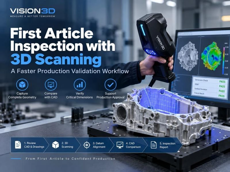
This is also why 3D scanning is increasingly used during first article inspection, where manufacturers often need to evaluate many dimensions and overall part geometry before production approval.
Full-Surface Inspection vs Point-Based Measurement
One of the most important differences between a CMM and a 3D scanner is the amount of geometry captured during inspection. A CMM typically measures specific points or features selected in advance, while a 3D scanner captures a dense representation of the complete visible surface.
This difference changes the type of questions engineers can answer.
Point-based measurement is highly effective when the inspection requirement is clearly defined, such as checking a hole diameter, distance between two features, or the position of a critical datum. Full-surface inspection becomes more valuable when engineers need to understand how the complete manufactured geometry differs from the nominal design.
Why Full-Surface Data Matters
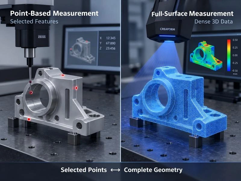
Dense 3D scan data can reveal geometric variation that may be difficult to understand from a limited number of measurement points. Engineers can evaluate the complete surface and visualize how deviation changes across different regions of the part.
Typical applications include:
- Surface profile inspection
- Overall warpage analysis
- Sheet metal deformation
- Springback evaluation
- Casting and molding variation
- Full-part CAD comparison
After the scanned data is aligned with the CAD model, inspection software can generate a 3D color deviation map showing where the manufactured surface is above, below, or within the specified geometric range.
This makes full-field measurement particularly useful when quality engineers need to understand the overall deviation pattern rather than only determine whether individual measurement points pass or fail.
Complex and Freeform Surfaces: Where 3D Scanning Has an Advantage
Complex freeform geometry is one of the clearest applications where 3D scanning can provide a practical advantage over traditional point-based measurement.
Components such as turbine blades, automotive body panels, cast housings, molds, dies, and complex tooling contain curved surfaces that cannot always be represented effectively by a small number of measurement points. A CMM can inspect these surfaces, but obtaining enough points to describe the complete geometry may require additional programming and measurement time.
3D scanning captures the visible surface continuously, creating dense geometric data that can be compared directly with the nominal CAD model.
Typical Complex-Part Applications
- Automotive sheet metal and body structures
- Turbine and aerospace components
- Die cast and molded parts
- Molds and dies
- Industrial tooling
- Complex machined surfaces
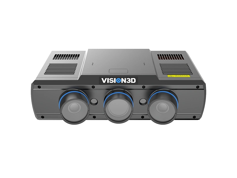
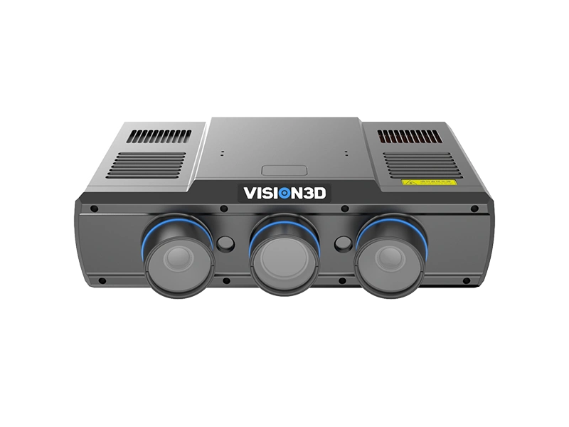
For precision components requiring high-density optical measurement, the PowerScan Series supports full-field dimensional inspection, while a metrology-grade handheld 3D scanner can provide greater flexibility when the component is large, difficult to move, or requires measurement from multiple positions.
The key advantage is not simply collecting more points. Dense surface data allows engineers to evaluate the complete shape of a component and identify geometric variation that could affect assembly, fit, or manufacturing performance.
GD&T Inspection: CMM or 3D Scanner?
Both CMMs and metrology 3D scanners can support dimensional and geometric inspection, but their suitability depends on the specific GD&T characteristic, tolerance level, datum structure, and feature accessibility.
CMMs remain particularly effective for critical discrete features and tightly controlled geometric relationships. 3D scanning can provide strong advantages for surface-related characteristics because dense data allows a much larger portion of the actual geometry to be evaluated.
| Inspection Characteristic | Typical Consideration |
|---|---|
| Surface Profile | 3D scanning provides dense data across complex surfaces |
| Flatness | Full-field scan data can evaluate variation across a broad surface |
| Critical Hole Position | CMM may be preferred where very tight feature tolerances are required |
| Internal Bore Geometry | CMM probing may provide better access than optical scanning |
| Complex Profile | 3D scanning can provide efficient full-surface comparison |
The measurement method should therefore be selected according to the engineering requirement rather than assuming that one technology is suitable for every GD&T characteristic. In many industrial workflows, full-surface 3D scanning and targeted tactile measurement are used together to achieve both broad geometric coverage and precise verification of critical features.
Large-Part Measurement: CMM vs 3D Scanner
Part size can significantly influence the choice between a CMM and a 3D scanner. Fixed CMMs operate within a defined measurement volume, which works well for components that fit comfortably within the machine envelope. As part dimensions increase, however, handling and positioning can become more difficult.
Portable 3D scanners provide greater flexibility because the measurement system can move around the component rather than requiring the entire part to be placed inside a fixed machine.
This is particularly useful for:
- Automotive body structures
- Large castings
- Aerospace components
- Heavy machinery
- Large molds and tooling
For components extending across several meters, maintaining dimensional relationships between different scanning areas also becomes important. In these applications, handheld 3D scanning can be combined with industrial photogrammetry to establish a global reference across the complete measurement volume.
For more demanding large-scale measurement projects, photogrammetry can help connect multiple scanning positions within one coordinate framework while the scanner captures detailed surface geometry. This approach is especially useful when the part cannot easily be moved or inspected within a conventional metrology room.
Portability and Shop-Floor Inspection
Measurement location is another practical difference between CMMs and 3D scanners. Fixed CMMs are commonly installed in controlled metrology environments where temperature, vibration, cleanliness, and machine stability can be carefully managed.
This controlled environment supports reliable precision measurement, but it may require manufacturers to transport components from the production area to the inspection room.
Handheld 3D scanners offer a different workflow. The measurement system can be brought directly to the part, allowing inspection in:
- Production workshops
- Assembly areas
- Supplier facilities
- Tooling departments
- Large equipment installation sites
A handheld metrology-grade 3D scanner can therefore be particularly useful when components are large, difficult to transport, or require measurement at different production stages.
Portable CMM systems also exist, so portability is not exclusive to 3D scanning. However, optical scanning generally provides an advantage when manufacturers need flexible full-surface measurement directly around the component.
Automated Inspection: CMM or 3D Scanning?
Both CMMs and 3D scanning systems can be integrated into automated inspection workflows. The best approach depends on whether the production process requires selected feature verification or complete surface inspection.
Automated CMM inspection is well established for repeatable measurement of defined dimensions and geometric features. Once the program is created, the machine can inspect the same characteristics consistently across multiple parts.
Automated 3D scanning is especially useful when manufacturers need broader geometric coverage. A robotic system can capture multiple areas of a component and automatically perform CAD comparison, deviation analysis, and digital reporting.
| Automated Inspection Requirement | Typical Approach |
|---|---|
| Repeatable critical feature measurement | CMM automation can provide stable programmed inspection |
| Full-surface inspection | Automated 3D scanning provides dense geometric coverage |
| Complex freeform components | 3D scanning can reduce feature-by-feature measurement requirements |
| Automated CAD comparison | 3D scanning supports direct full-field deviation analysis |
For high-volume production environments, an automated 3D inspection system can provide repeatable scanning paths, standardized data acquisition, and faster digital quality feedback across production batches.
When Should You Choose a CMM?
A CMM is often the stronger starting point when the inspection requirement focuses on a limited number of critical geometric features that require highly controlled tactile measurement.
Typical situations include:
- Very tight tolerances on critical dimensions
- Precision holes and cylindrical features
- Deep or internal geometries accessible to a probe
- Simple prismatic components
- Existing validated CMM inspection programs
- Customer or quality procedures that specifically require tactile measurement
For these applications, the ability to measure defined features within a controlled coordinate system can be more important than collecting large amounts of surface data.
When Should You Choose a 3D Scanner?
3D scanning becomes more attractive when the inspection task requires broad geometric coverage, complex surface measurement, or rapid comparison between the manufactured component and CAD data.
Typical applications include:
- Complex freeform surfaces
- Large numbers of inspection features
- Full-surface dimensional inspection
- 3D color deviation analysis
- Large or difficult-to-move components
- Sheet metal, casting, and molded-part inspection
- Shop-floor or supplier-site measurement
- Rapid first article inspection
For high-accuracy optical measurement of precision components, the PowerScan Series provides full-field blue light 3D measurement, while portable scanning solutions can support larger or more complex inspection environments.
The main advantage is not simply faster data collection. A 3D scanner provides a much more complete digital description of the part, allowing engineers to evaluate both individual features and broader geometric variation from the same dataset.
Can CMM and 3D Scanning Be Used Together?
In many manufacturing environments, the most effective dimensional inspection strategy is not choosing between a CMM and a 3D scanner, but combining both technologies according to the measurement requirement.
A 3D scanner can first capture the complete component and identify areas of dimensional concern. Engineers can then use a CMM to verify specific features that require tighter tolerances, tactile probing, or access to internal geometry.
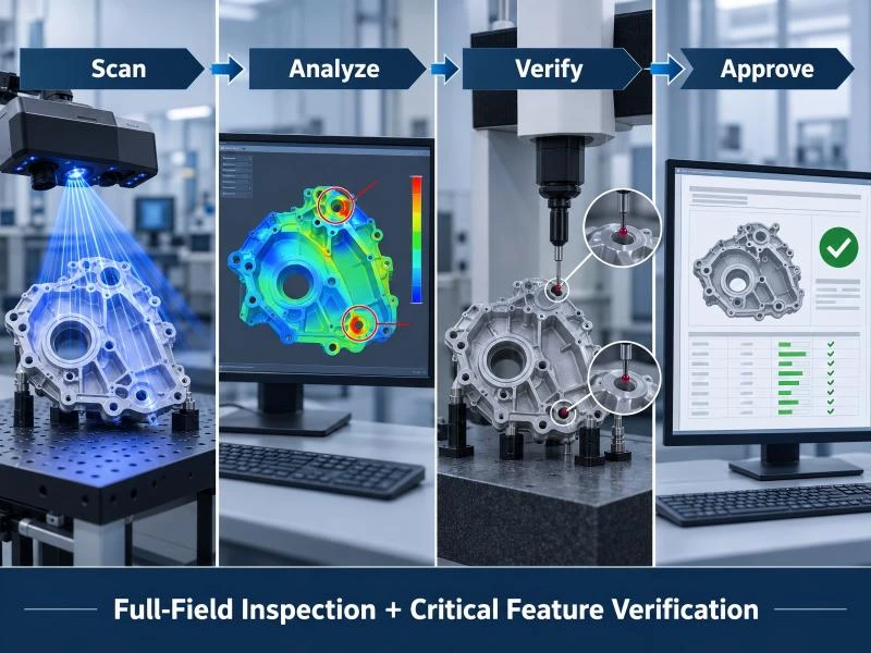
A hybrid workflow may look like:
3D Scan → Full-Surface Analysis → Identify Critical Areas → CMM Verification → Final Inspection Decision
This approach allows manufacturers to combine the strengths of both technologies:
- Full-field geometric coverage from 3D scanning
- Precise feature verification from CMM measurement
- Faster identification of manufacturing variation
- More focused use of CMM inspection time
For complex industrial components, this combination can provide a more complete understanding of part quality than relying on either method alone.
Which Measurement System Is Right for Your Application?
The right choice depends on the part, tolerance, geometry, measurement environment, and type of inspection data required.
| Your Measurement Requirement | Better Starting Point |
|---|---|
| Very tight critical dimensions | CMM |
| Full-surface deviation analysis | 3D Scanner |
| Complex freeform geometry | 3D Scanner |
| Deep internal features | CMM |
| Large or difficult-to-move component | Portable 3D Scanner |
| Shop-floor dimensional inspection | Portable 3D Scanner |
| Small number of critical GD&T features | CMM |
| Many features plus surface analysis | 3D Scanner |
| Mixed precision and full-field requirements | Hybrid Workflow |
Instead of asking which technology is universally better, manufacturers should begin by defining what needs to be measured and what information is required from the inspection process. This makes it easier to select a system that supports both quality requirements and production efficiency.
VISION3D Solutions for Dimensional Inspection
When 3D scanning is the better fit for an inspection task, the next step is choosing a measurement system that matches the required accuracy, part size, geometry, and inspection environment. VISION3D provides different 3D measurement solutions for precision inspection, portable measurement, automation, and large-volume applications.
| Inspection Requirement | VISION3D Solution |
|---|---|
| High-accuracy full-field dimensional inspection | PowerScan Series blue light 3D scanner |
| Portable measurement of complex or large parts | VScan M Series handheld 3D scanner |
| Repeatable automated production inspection | AutoScan automated 3D inspection system |
| Large-volume measurement and global reference | VMetric industrial photogrammetry system |
The correct system should be selected according to the actual inspection requirement rather than part type alone. A precision machined component may prioritize measurement accuracy, while a vehicle body or large casting may place greater emphasis on portability, full-surface coverage, and large measurement volume.
FAQ About CMM vs 3D Scanner
Is a CMM more accurate than a 3D scanner?
A high-precision CMM can provide excellent accuracy for critical point-based measurements and tightly toleranced features. Metrology-grade 3D scanners can also provide high-accuracy dimensional data, but their main advantage is capturing dense full-surface geometry. The required tolerance and measurement task should determine which technology is more appropriate.
Can a 3D scanner replace a CMM?
In some applications, yes, particularly when the inspection focuses on complex surfaces, full-part CAD comparison, deformation analysis, or large components. However, a CMM may still be preferred for deep internal features, very tight tolerances, or specific tactile measurement requirements. Many manufacturers use both technologies together.
Can 3D scanners measure GD&T?
Yes. Metrology-grade 3D scanning data can support inspection of many geometric characteristics, including surface profile, flatness, position, and other dimensional requirements. The suitability depends on feature accessibility, tolerance, alignment method, scanner capability, and inspection software.
Which is faster, a CMM or a 3D scanner?
For a small number of predefined features, a CMM can be very efficient. For complex parts with many features or large surface areas, 3D scanning can collect substantially more geometric information in a single measurement workflow and reduce repeated point-by-point inspection.
Which is better for large or complex parts?
Portable 3D scanners are often more flexible for large, freeform, or difficult-to-move components because the scanner can move around the part and capture dense surface data from multiple positions. For very large measurement volumes, 3D scanning can also be combined with photogrammetry to maintain a stable global reference.
Conclusion
The choice between a CMM and a 3D scanner depends on the type of dimensional information required. CMMs remain highly effective for precise tactile measurement of critical features, controlled datum relationships, and internal geometry that can be accessed with a probe.
3D scanning provides a different advantage by capturing dense full-surface data. It is particularly valuable for complex freeform geometry, CAD comparison, deformation analysis, large components, portable inspection, and applications where manufacturers need to understand the overall condition of a part rather than only selected measurement points.
For many manufacturers, the most effective strategy is not choosing one technology exclusively. Combining full-field 3D scanning with targeted CMM verification can provide both broad geometric coverage and precise feature measurement.
The right decision should therefore begin with four questions: What tolerance is required? What geometry must be measured? How much surface information is needed? Where will the inspection take place? Once these requirements are clear, manufacturers can choose the measurement method that best supports both quality control and production efficiency.