3D Scanner Calibration: When, Why and How to Calibrate an Industrial Scanner
Industrial 3D scanners are widely used for dimensional inspection, CAD comparison, reverse engineering, and automated quality control. In these applications, measurement reliability depends not only on scanner specifications but also on whether the measurement system is correctly calibrated.
Transportation, mechanical shock, temperature changes, maintenance, component replacement, and long-term use can affect the geometric relationship between cameras, projectors, sensors, or other optical components. Even small changes may influence dimensional results when the scanner is used for high-accuracy industrial measurement.
3D scanner calibration helps ensure that the measurement system continues to operate within its intended performance. It establishes or updates the relationship between the scanner and a known reference, allowing the system to correctly interpret captured optical data as dimensional information.
For quality engineers, calibration is especially important before critical dimensional inspection, repeated production measurement, or any workflow where scanned data is used to make pass/fail decisions.
What Is 3D Scanner Calibration?
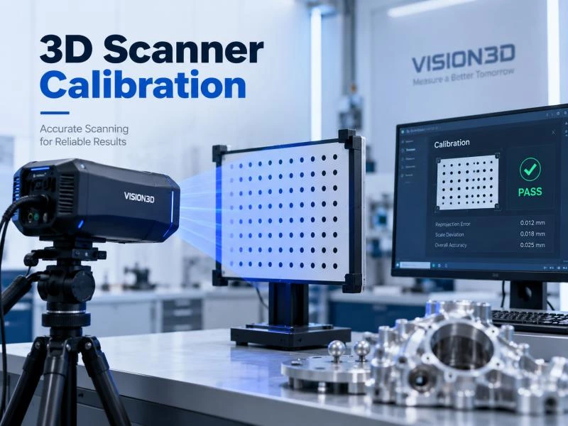
3D scanner calibration is the process of establishing and verifying the geometric relationship between the scanner's measurement components and a known reference standard. Depending on the scanner design, this may involve cameras, projectors, optical sensors, calibration targets, scale references, or other certified artifacts.
During calibration, the scanner captures reference features with known dimensions or positions. The system then compares the measured data with the expected reference values and calculates the parameters required to maintain accurate 3D reconstruction.
For an optical 3D scanner, calibration may account for factors such as:
- Camera position and orientation
- Projector-to-camera geometry
- Lens distortion
- Measurement scale
- Sensor alignment
- Working distance and measurement volume
The exact procedure varies between scanner technologies. A fixed structured light scanner may use a dedicated calibration panel, while a handheld system may require calibration across several positions or orientations. Large-volume measurement and photogrammetry systems may also use scale bars or other reference artifacts to establish dimensional scale.
Calibration Is Not the Same as Point Cloud Alignment
Calibration is sometimes confused with point cloud alignment, but the two processes serve different purposes.
Calibration concerns the measurement system itself. Its purpose is to ensure that the scanner correctly converts optical observations into dimensional data.
Alignment takes place after data acquisition. It determines how scan data is positioned relative to another scan, a coordinate system, or a CAD model.
For example, best-fit alignment may reposition a scanned component so that it matches CAD geometry as closely as possible, but it cannot correct an improperly calibrated scanner. If the measurement system contains a scale or geometric error, changing the alignment method does not remove that underlying measurement error.
This distinction is important in industrial metrology because reliable inspection requires both a correctly calibrated measurement system and an appropriate alignment strategy.
Why Is 3D Scanner Calibration Important?
Calibration directly affects whether dimensional data can be trusted. A scanner may still produce a visually complete 3D model even when its measurement condition has changed, but the resulting dimensions may no longer meet the accuracy required for inspection.
Reliable calibration helps support:
- Consistent dimensional inspection results
- Accurate CAD-to-scan comparison
- Reliable surface deviation analysis
- More confident GD&T evaluation
- Repeatable production inspection
- Traceable quality documentation
In a quality-control workflow, small systematic measurement errors can affect multiple features across the same part. If the data is used for first article inspection, tooling adjustment, or batch acceptance, an undetected calibration problem may lead to incorrect engineering decisions.
Calibration therefore should not be treated only as a maintenance task. For industrial measurement, it is part of maintaining confidence in the entire inspection process.
Calibration vs Verification: What Is the Difference?
Calibration and verification are closely related, but they are not the same process. Understanding the difference is important because an industrial 3D scanner does not necessarily need a full recalibration every time its measurement condition is checked.
What Is Calibration?
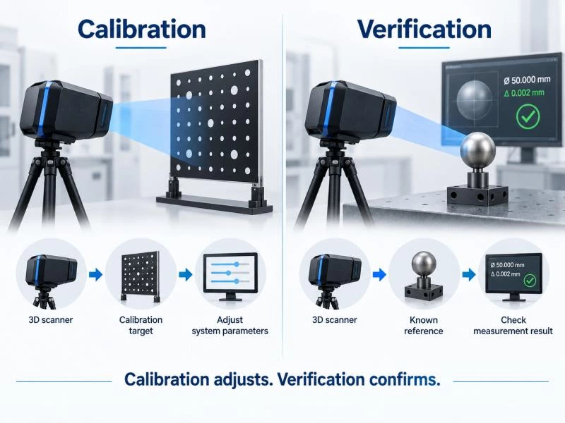
Calibration establishes or updates the relationship between the scanner and a known reference. Depending on the system, this may involve adjusting optical geometry, measurement scale, camera relationships, or other internal parameters so that the scanner can correctly reconstruct dimensional data.
Calibration may be required when the measurement system has been transported, repaired, physically disturbed, or exposed to environmental changes that could affect measurement performance.
What Is Verification?
Verification checks whether the scanner is currently performing within an acceptable measurement range. Instead of changing the scanner configuration, the system measures a known reference artifact and compares the result with its certified or expected dimensions.
A verification check can help answer questions such as:
- Is the scanner still measuring within the required tolerance?
- Has measurement performance changed since the previous inspection?
- Is full recalibration necessary?
- Can the system be used for the planned dimensional inspection?
In practical quality-control workflows, verification may be performed more frequently than full calibration. For example, a scanner used for routine production inspection may be checked against a reference artifact before a critical measurement task. If the verification result remains within the defined limits, full recalibration may not be necessary.
A useful way to distinguish the two is:
Calibration establishes the measurement relationship; verification confirms that the relationship is still reliable.
When Should a 3D Scanner Be Calibrated?
There is no universal calibration interval that applies to every industrial 3D scanner. Calibration requirements depend on scanner design, measurement tolerance, operating environment, transportation frequency, usage conditions, and the manufacturer's maintenance recommendations.
Instead of relying only on a fixed schedule, manufacturers should also consider events that may affect the scanner's measurement geometry or stability.
| Situation | Why Calibration or Verification May Be Needed |
|---|---|
| Initial installation | Confirms that the system is correctly configured before production measurement begins. |
| After transportation | Movement and vibration may affect optical or mechanical relationships within the scanner. |
| After impact or mechanical shock | Even small physical changes can influence camera, projector, or sensor alignment. |
| After repair or component replacement | Changes to optical, mechanical, or electronic components may alter the original measurement condition. |
| After significant temperature change | Thermal expansion and contraction can affect the geometry of precision measurement systems. |
| Before critical inspection | A verification check can provide additional confidence before high-tolerance or acceptance-critical measurements. |
| When measurement results become inconsistent | Unexpected drift, poor repeatability, or unusual dimensional differences may indicate that verification or recalibration is required. |
| According to a scheduled quality plan | Periodic checks help maintain measurement traceability and support internal quality-control procedures. |
After Transportation or Relocation
Portable and handheld 3D scanners are frequently moved between workshops, production lines, supplier sites, or customer facilities. Transportation can expose equipment to vibration, temperature variation, or accidental mechanical shock.
For this reason, a verification check is recommended after significant transportation, especially when the scanner will be used for tight-tolerance dimensional inspection. If the verification result falls outside the expected range, recalibration may be required before measurement continues.
After Mechanical Impact
A scanner that has been dropped, struck, or exposed to excessive vibration should not immediately be assumed to remain within its previous measurement condition.
Even if there is no visible damage, small changes in optical alignment can affect dimensional accuracy. Verification against a known reference is therefore important before the system returns to production use.
After Repair or Optical Component Replacement
Replacing a camera, projector, lens, sensor, or other measurement-related component can change the geometry of the scanning system. In these situations, recalibration is generally necessary because the original calibration parameters may no longer represent the updated hardware configuration.
After Significant Environmental Changes
Industrial 3D measurement systems are sensitive to environmental conditions, particularly temperature. If a scanner is moved between environments with significantly different temperatures, it should be allowed to stabilize before calibration or precision measurement.
Calibration performed while the scanner or reference artifact is still changing temperature can introduce unnecessary uncertainty into the process.
Before High-Accuracy or Critical Inspection
Not every measurement task requires the same level of confidence. A quick prototype scan and a final acceptance inspection do not carry the same quality risk.
Before applications such as first article inspection, production approval, tooling compensation, or other critical dimensional verification, manufacturers may perform a reference measurement to confirm that the scanner remains within the required performance limits.
When Verification Results Begin to Drift
One of the most useful indicators is a change in repeated measurements of the same reference artifact. If dimensions that were previously stable begin to shift, the cause should be investigated before continuing production inspection.
The issue may be related to calibration, environmental conditions, target condition, scanner hardware, or the verification procedure itself. Recalibration should therefore be based on measured evidence rather than performed automatically without identifying the source of the change.
How Often Should an Industrial 3D Scanner Be Calibrated?
Calibration frequency should be based on measurement risk rather than a universal time interval. A scanner used occasionally in a controlled laboratory may require a different calibration strategy from a handheld system transported between factories every week.
Important factors include:
- Required measurement tolerance
- Frequency of scanner use
- Transportation and relocation
- Environmental stability
- Production quality requirements
- Internal quality procedures
- Manufacturer recommendations
For many industrial applications, a practical approach is to combine scheduled calibration with more frequent verification. This allows manufacturers to monitor measurement performance without performing unnecessary full recalibration when the system remains stable.
How to Calibrate a 3D Scanner Step by Step
The exact calibration procedure depends on the scanner type, optical configuration, and manufacturer's software. However, most industrial 3D scanner calibration workflows follow the same general principle: stabilize the system, measure a known reference, calculate the difference between measured and expected values, apply the required correction, and verify the result.
Calibration should always be performed according to the procedure specified for the scanner. Using the wrong target, working distance, environmental condition, or calibration sequence can reduce the reliability of the result.
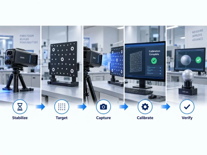
Step 1: Stabilize the Scanner and Measurement Environment
Before calibration begins, both the scanner and the calibration artifact should be allowed to reach a stable condition. Temperature changes can affect optical systems, mechanical structures, and the physical dimensions of reference artifacts, particularly in high-accuracy measurement applications.
The calibration area should also minimize factors that may interfere with the process, including:
- Strong vibration
- Rapid temperature changes
- Unstable or excessive ambient light
- Dust or contamination on optical components
- Airflow directly affecting precision equipment
If the scanner manufacturer specifies a warm-up period, the system should complete that period before calibration starts. Performing calibration immediately after moving equipment from a cold storage area into a warmer inspection room, for example, may produce less reliable results because the scanner has not yet reached thermal equilibrium.
Step 2: Inspect and Prepare the Calibration Artifact
The calibration artifact provides the known reference against which the scanner evaluates its measurement geometry. Its condition directly affects the quality of the calibration process.
Before use, check that the calibration board, scale bar, sphere, or other reference artifact is:
- Clean and free from dust or oil
- Not scratched, bent, or physically damaged
- Stored and handled according to the manufacturer's instructions
- Suitable for the scanner model being calibrated
- Within its required certification or verification status when traceability is needed
A damaged calibration target can introduce errors into the calibration process even if the scanner itself is functioning correctly. Calibration artifacts should therefore be treated as precision measurement tools rather than ordinary accessories.
Step 3: Position the Scanner and Reference Correctly
The scanner and reference artifact must be positioned according to the required calibration geometry. Depending on the system, the procedure may specify particular distances, angles, orientations, or positions within the measurement volume.
For structured light systems, the scanner may need to observe a calibration panel from several defined orientations. A handheld scanner may require the operator to capture the calibration target from multiple distances or viewing angles. Large-volume systems may require several reference points distributed throughout the measurement area.
The goal is to provide enough known geometric information for the system to evaluate the relationship between its measurement components across the intended operating range.
Step 4: Capture the Reference Measurements
Once the scanner and artifact are positioned correctly, the calibration software captures a series of reference measurements.
Depending on the scanner design, the system may analyze:
- Known feature spacing
- Reference dimensions
- Target positions
- Camera-to-projector geometry
- Lens distortion
- Measurement scale
- Spatial relationships across the working volume
During this stage, the operator should follow the software prompts carefully and avoid moving the reference artifact outside the required position or distance range.
Step 5: Calculate and Apply Calibration Parameters
After the reference data has been captured, the calibration software compares the measured geometry with the known reference values.
The system may then calculate corrections related to:
- Scale
- Optical distortion
- Camera orientation
- Projector geometry
- Sensor position
- Measurement volume relationships
These parameters help the scanner convert optical observations into dimensional coordinates more accurately during subsequent measurement.
Operators normally should not manually alter calibration parameters unless the scanner manufacturer specifically provides such controls. Modern industrial systems generally calculate and apply the required parameters through dedicated calibration software.
Step 6: Verify the Calibration Result
Calibration should not end when the software reports that the procedure has been completed. The measurement result should be verified using a known reference whenever the application requires dimensional confidence.
A verification check can include:
- Measuring a certified reference artifact
- Comparing measured dimensions with known values
- Repeating the same measurement several times
- Checking measurement consistency at different positions
- Confirming that the result remains within the required tolerance
If the verification result is outside the acceptable range, the operator should investigate the cause before using the scanner for production inspection. Possible causes may include an incorrect calibration procedure, environmental instability, target damage, optical contamination, or a hardware issue.
What Calibration Tools and Reference Artifacts Are Used?
Different 3D measurement systems use different calibration and verification artifacts. The reference should match the measurement principle and the type of performance being evaluated.
Calibration Board or Calibration Panel
Calibration boards are commonly used with optical and structured light scanners. They contain accurately defined patterns or features that allow the system to evaluate camera geometry, projector relationships, lens distortion, and measurement scale.
The board should be positioned at the distances and orientations specified by the calibration procedure. Using an incorrect board or one with damaged reference features can affect the calibration result.
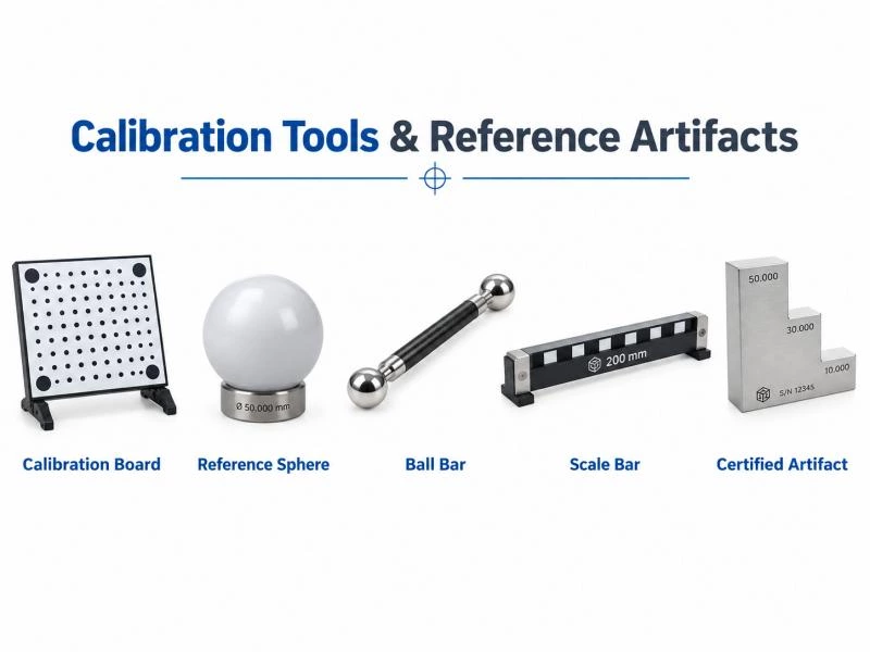
Reference Spheres
Precision spheres can be used to evaluate geometric measurement performance because their known diameter and form provide a stable reference for three-dimensional measurement.
Multiple spheres positioned within a measurement volume can also help evaluate spatial relationships between different areas of the scanner's working range.
Ball Bars and Ball Plates
Ball bars and ball plates contain accurately positioned spherical features with known distances between them. They can be useful for evaluating dimensional relationships across a larger area rather than checking only a single local dimension.
These artifacts are particularly useful when measurement performance across the working volume is important.
Scale Bars
Scale bars provide a known distance between reference points and are especially important in photogrammetry and large-volume measurement.
They help establish dimensional scale within a reference network, reducing the risk that a large measurement project produces geometrically consistent but incorrectly scaled results.
Certified Dimensional Artifacts
Certified artifacts with known dimensions can be used to verify whether a scanner continues to measure within the required performance range.
Depending on the quality system, these artifacts may be traceable to recognized measurement standards and supported by calibration documentation.
What Factors Can Affect 3D Scanner Calibration Quality?
Even when the correct calibration procedure is followed, environmental conditions, equipment status, and reference setup can influence the reliability of the result. These factors are especially important when the scanner is used for tight-tolerance dimensional inspection.
| Factor | How It Affects Calibration | Recommended Practice |
|---|---|---|
| Temperature Stability | Rapid temperature changes can affect both scanner geometry and the physical dimensions of calibration artifacts. | Allow the scanner and reference artifact to stabilize in the measurement environment before calibration. |
| Vibration | Movement from machinery, unstable tables, or nearby equipment can disturb the relative position of the scanner and reference artifact. | Perform calibration on a stable measurement surface away from significant vibration. |
| Calibration Target Condition | Dirt, scratches, deformation, or improper storage can change the reference features used during calibration. | Inspect and clean calibration artifacts regularly and protect them from physical damage. |
| Working Distance & Position | Calibration outside the scanner's specified working range can prevent the system from correctly determining its measurement geometry. | Follow the required target distance, angle, and position defined by the scanner calibration procedure. |
| Optical Cleanliness | Dust, fingerprints, or contamination on lenses, cameras, projectors, or protective covers can reduce image quality. | Keep optical surfaces clean and maintain them according to the equipment manufacturer's instructions. |
| Scanner Warm-Up | Precision optical and electronic components may change slightly before reaching a stable operating condition. | Complete the manufacturer's recommended warm-up period before calibration and precision measurement. |
In practice, calibration quality depends on controlling several conditions at the same time. A clean calibration target cannot compensate for an unstable temperature, just as a stable environment cannot correct an incorrect working distance. Consistent setup and verification are therefore essential for reliable measurement results.
Calibration Standards and Measurement Traceability
For industrial dimensional inspection, calibration is not only about completing a software procedure. The measurement result may also need to be traceable and evaluated against recognized metrology requirements, particularly in automotive, aerospace, precision manufacturing, and supplier quality control.
Different standards apply to different measurement technologies and evaluation methods. The applicable standard depends on the scanner type, measurement configuration, customer requirements, and quality-management system.
VDI/VDE 2634
VDI/VDE 2634 is widely referenced for evaluating optical 3D measuring systems. It provides methods for assessing measurement performance using calibrated artifacts and defined test procedures.
Depending on the type of optical measuring system, evaluation may consider characteristics such as:
- Probing or form measurement error
- Sphere spacing error
- Length measurement error
- Measurement performance within a defined working volume
For industrial users, these tests provide a more meaningful indication of measurement capability than relying only on point density or image resolution.
ISO 10360-13
ISO 10360-13 addresses acceptance and reverification testing for optical 3D coordinate measuring systems. It provides a standardized framework for evaluating dimensional measurement performance under defined conditions.
For procurement and quality teams, a scanner specification supported by a recognized evaluation method can make it easier to compare measurement capability and define acceptance criteria for a specific inspection application.
ISO/IEC 17025 and Traceable Calibration
ISO/IEC 17025 relates to the competence of testing and calibration laboratories. When a calibration or verification artifact is supported by an accredited laboratory, its certified values can provide documented traceability for the measurement process.
Traceability means that a measurement result can be related to recognized reference standards through a documented chain of calibrations, each contributing to the overall measurement uncertainty.
This becomes especially important when 3D scan data is used for:
- Supplier acceptance
- First article inspection
- Customer quality documentation
- Process capability studies
- Tooling approval
- Production release decisions
Not every scanning task requires accredited calibration documentation. For reverse engineering, visualization, or less critical dimensional work, internal verification may be sufficient. The required level of traceability should therefore match the measurement risk and customer requirements.
How to Build a Practical 3D Scanner Calibration Strategy
A reliable calibration strategy should combine scheduled maintenance with condition-based verification. Calibrating too infrequently increases the risk of unnoticed measurement drift, while unnecessary recalibration can interrupt production without adding meaningful measurement confidence.
A practical industrial approach can include the following steps:
- Define the required measurement tolerance. Determine how accurate the inspection result needs to be for the part and process.
- Follow the scanner manufacturer's calibration procedure. Use the correct artifact, software, working distance, and environmental conditions.
- Establish a verification routine. Measure a known reference at appropriate intervals or before critical inspection tasks.
- Record measurement history. Track deviations over time to identify gradual changes in system performance.
- Recalibrate after significant events. Transportation, impact, repair, component replacement, or failed verification may require recalibration.
- Use traceable references when required. Critical dimensional inspection may require certified artifacts and documented calibration records.
The objective is not simply to calibrate as often as possible. The objective is to maintain evidence that the scanner remains suitable for its intended measurement task.
VISION3D Calibration and Measurement Support
Industrial users often need more than the initial scanner setup. Long-term measurement reliability also depends on correct calibration procedures, verification methods, maintenance, and technical support.
VISION3D provides technical support for industrial 3D measurement systems, including calibration guidance, measurement verification, maintenance support, and accuracy calibration services according to project requirements.
For applications that require documented measurement performance, calibration and verification requirements can be considered together with scanner configuration, part tolerance, measurement volume, and production environment.
Users can also refer to VISION3D's after-sales service for support related to equipment maintenance, calibration, and long-term measurement performance.
Frequently Asked Questions About 3D Scanner Calibration
How often should a 3D scanner be calibrated?
There is no single calibration interval suitable for every scanner. Frequency depends on scanner design, usage, transportation, environmental stability, required tolerance, manufacturer recommendations, and internal quality procedures. A practical strategy usually combines scheduled calibration with more frequent verification checks.
Does a 3D scanner need recalibration every time it is moved?
Not necessarily. Small movements within a stable inspection area may not require full recalibration. However, after long-distance transportation, significant vibration, mechanical impact, or major temperature change, verification should be performed before critical dimensional inspection. Recalibration may be required if the verification result falls outside the acceptable range.
What is the difference between calibration and verification?
Calibration establishes or updates the relationship between the scanner and a known reference. Verification checks whether the scanner is still measuring within the required performance range. Verification therefore does not necessarily change the scanner's internal calibration parameters.
Can calibration make a 3D scanner more accurate?
Calibration can help restore or maintain the scanner's intended measurement performance, but it cannot make the system more accurate than its fundamental design capability. Scanner accuracy also depends on hardware configuration, measurement volume, environmental conditions, measurement strategy, and application requirements.
What happens if a 3D scanner is not calibrated correctly?
An incorrectly calibrated scanner may still produce a visually complete 3D model, but dimensional values can contain systematic errors. These errors may affect CAD comparison, deviation analysis, GD&T evaluation, first article inspection, or production acceptance decisions.
Is calibration the same for handheld, structured light, and photogrammetry systems?
No. Different measurement technologies use different calibration procedures and reference artifacts. Fixed optical scanners may use dedicated calibration panels, handheld systems may require multi-position calibration, and photogrammetry systems commonly rely on scale references and target networks. The correct method should follow the scanner manufacturer's specified procedure.
Conclusion
3D scanner calibration is a fundamental part of reliable industrial measurement. It helps ensure that the relationship between the scanner, its optical components, and known dimensional references remains correct over time.
For most industrial users, the most effective strategy is not simply to recalibrate at fixed intervals. A stronger approach combines proper calibration, routine verification, stable environmental conditions, traceable reference artifacts, and measurement records.
Calibration cannot increase a scanner beyond its designed measurement capability, but it helps ensure that the system continues to perform within its intended accuracy. For dimensional inspection, CAD comparison, automated quality control, and other metrology applications, that confidence is essential for making reliable engineering decisions.