Blue Light 3D Scanner: How It Works and Industrial Applications
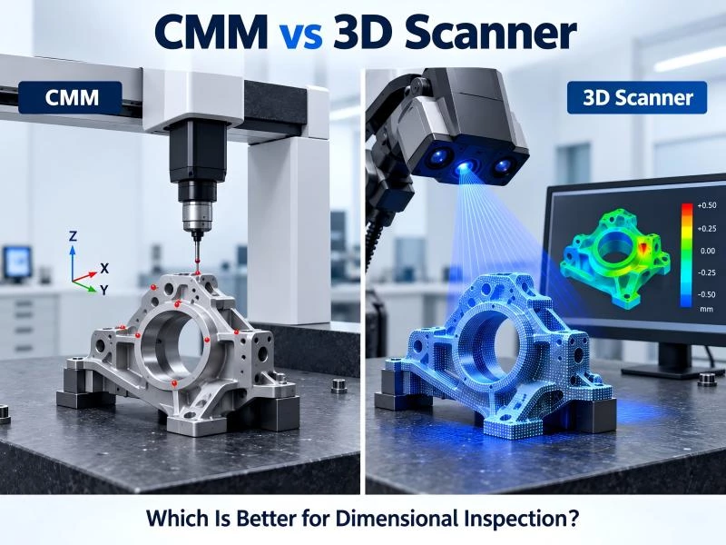
Manufacturers today collect far more dimensional data than they did only a decade ago. Electric vehicles, lightweight materials, precision machining, and automated production have significantly increased the demand for fast, reliable, and repeatable inspection methods. While traditional contact measurement remains an important part of industrial metrology, it is often less efficient when engineers need to evaluate complete surfaces, complex geometries, or hundreds of production parts within limited inspection cycles.
As manufacturing continues to move toward digital quality control, optical 3D measurement has become an essential technology across industries. Rather than measuring only a few predefined features, optical systems capture complete surface geometry, allowing engineers to understand not only whether a part is within tolerance, but also how and where dimensional variation occurs.
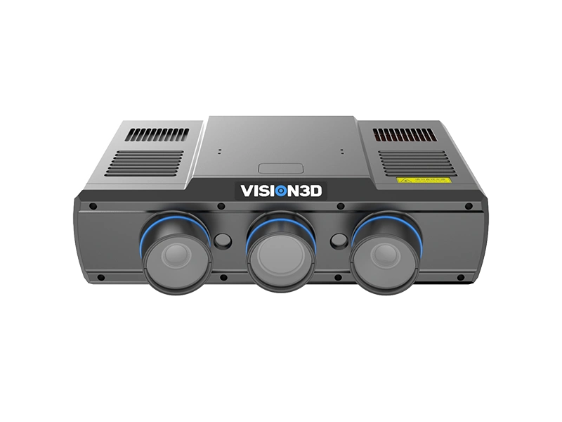
Among today's optical measurement technologies, the blue light scanner has become one of the most widely adopted solutions for industrial inspection. By combining blue structured light projection, stereo vision, and optical triangulation, these systems rapidly generate high-density 3D data for dimensional inspection, CAD comparison, reverse engineering, and manufacturing analysis.
This article explains how blue light scanning works, why manufacturers increasingly rely on blue structured light technology, and where it delivers the greatest value throughout modern manufacturing processes.
From Light Patterns to Digital Geometry
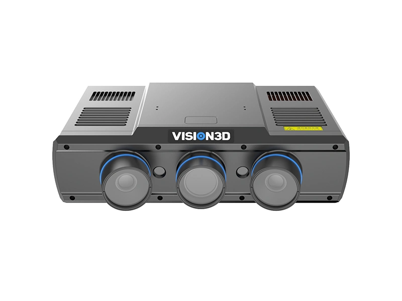
Although commonly referred to as a scanner, a blue light scanner is fundamentally an optical measurement system rather than a conventional imaging device. Its purpose is not to produce photographs of a component, but to convert physical geometry into accurate digital measurement data that can be analyzed throughout the manufacturing process.
Instead of touching a workpiece with a probe, the scanner projects precisely controlled blue light patterns onto the object's surface. Industrial cameras observe how these projected patterns deform across curves, holes, ribs, edges, and freeform surfaces. Sophisticated reconstruction algorithms then calculate millions of three-dimensional coordinates, generating a highly detailed digital representation of the part.
Unlike traditional measurement methods that collect only selected dimensions, blue light scanning captures complete surface information. Engineers can evaluate overall shape, local deformation, assembly interfaces, surface profiles, and geometric relationships from a single digital dataset, making inspection both more comprehensive and more efficient.
The resulting data can be used for a wide variety of engineering tasks, including:
- CAD comparison and deviation analysis
- Surface profile inspection
- Hole position verification
- GD&T evaluation
- Reverse engineering
- Digital quality documentation
Because measurement is completely non-contact, blue light scanners are also well suited for inspecting thin sheet metal, lightweight structures, precision machined components, molded parts, castings, and delicate surfaces that may be influenced by traditional contact measurement.
Rather than capturing images, a blue light scanner captures measurable geometry. This distinction is what makes blue structured light technology an important tool for modern industrial metrology.
Why Manufacturers Prefer Blue Structured Light
Not every optical measurement system uses the same light source. Depending on the application, manufacturers may encounter white structured light, laser scanning, or blue structured light technologies. Each has its own advantages, but blue structured light has become the preferred solution for many industrial inspection tasks because it offers an excellent balance between data quality, measurement stability, and inspection efficiency.
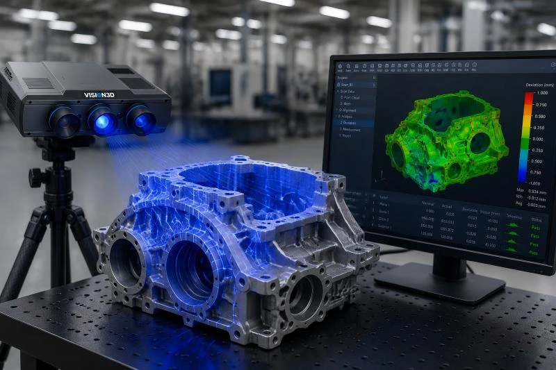
Its popularity is not simply determined by the color of the projected light. Instead, it results from a combination of optical characteristics that improve how projected patterns are detected, reconstructed, and converted into reliable measurement data under real manufacturing conditions.
| Optical Characteristic | Manufacturing Benefit |
|---|---|
| Narrow blue wavelength | Reduced influence from surrounding ambient light |
| High fringe contrast | Improved edge definition and surface reconstruction |
| Dense area projection | Complete full-field measurement instead of point sampling |
| Stable optical projection | Consistent automated inspection across production batches |
One of the primary advantages of blue structured light is its relatively narrow wavelength, typically around 450–470 nm. Optical filters inside the scanner can efficiently isolate this wavelength from much of the surrounding illumination commonly found in production workshops. As a result, projected fringe patterns remain clearer, allowing the cameras to distinguish subtle geometric changes more consistently during image acquisition.
Blue structured light also produces high-contrast fringe patterns that improve the reconstruction of complex surfaces. Features such as sharp edges, narrow slots, small holes, thin ribs, and freeform transitions can often be reconstructed with greater consistency because the projected patterns remain well defined across changing geometry.
Equally important is the ability to acquire complete surface information within each scan. Rather than evaluating isolated measurement points, engineers receive dense point cloud data covering the visible surface of the component. This full-field measurement capability allows inspection software to reveal deformation trends, surface variation, and assembly conditions that may not be visible through traditional sampling methods.
These characteristics have made blue structured light particularly suitable for automated inspection. When integrated with robotic systems, standardized scanning paths, and digital inspection software, manufacturers can perform repeatable measurements throughout production while reducing operator variability and improving inspection consistency.
How a Blue Light Scanner Measures an Object
Although the scanning process appears simple from the outside, every measurement performed by a blue light scanner is the result of several coordinated optical and computational steps. Rather than recording images like a conventional camera, the system continuously transforms projected light into measurable three-dimensional coordinates. Each stage contributes to the quality of the final point cloud and ultimately determines how effectively engineers can evaluate the manufactured part.
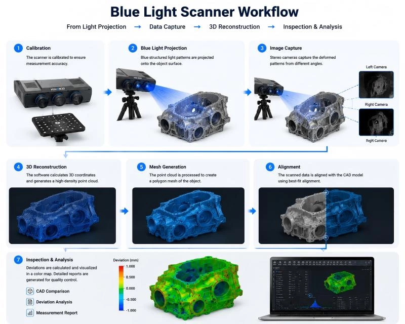
While individual scanner designs vary, most industrial blue light scanners follow the same measurement workflow from data acquisition to digital inspection.
Projecting Structured Blue Light
The measurement process begins by projecting a sequence of precisely coded blue light patterns onto the workpiece. These patterns are carefully designed rather than being simple illumination. As they fall across curved surfaces, holes, ribs, edges, and other geometric features, the projected fringes become distorted according to the shape of the object.
Every change in the projected pattern contains spatial information. Instead of measuring individual dimensions directly, the scanner first captures these optical variations, creating the foundation for three-dimensional reconstruction.
Stereo Image Acquisition
One or more high-resolution industrial cameras observe the projected patterns from different viewing positions. Because each camera sees the same surface from a unique angle, the system obtains multiple perspectives of every visible feature.
Unlike conventional photography, the cameras are not interested in the color or appearance of the object itself. Their primary task is to record the precise position of every projected fringe so that the reconstruction software can determine where each point exists in three-dimensional space.
Optical Triangulation and 3D Reconstruction
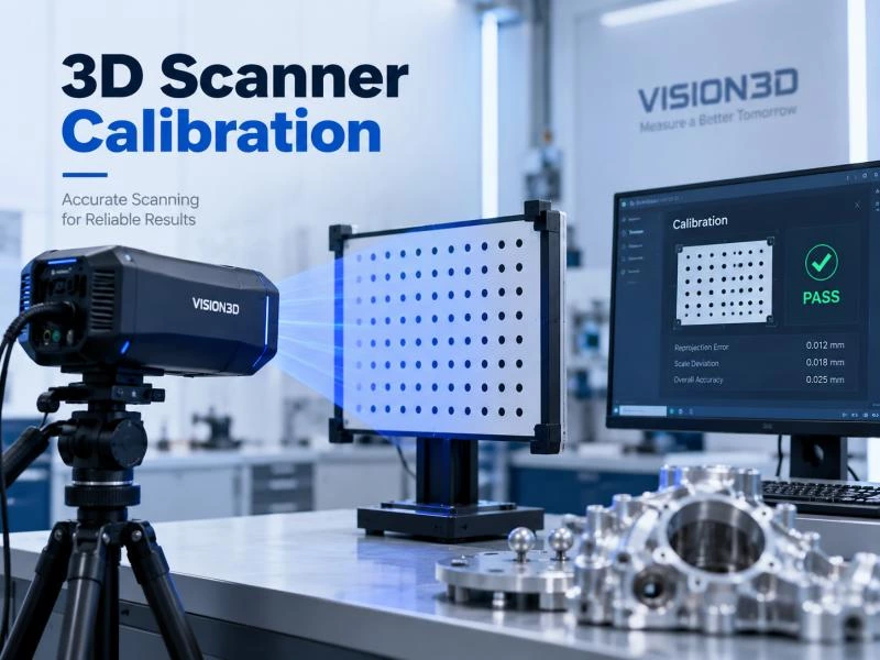
Once the projected patterns have been captured, the scanner applies optical triangulation to calculate three-dimensional coordinates. Since the geometric relationship between the projector and the cameras has already been calibrated, the software can determine the exact spatial location of every visible point by analyzing how the projected patterns appear from different viewing angles.
This calculation is repeated across the entire measurement area, producing millions of coordinate points within only a few seconds. Instead of generating isolated measurement values, the system creates a dense digital representation of the complete visible surface.
Building a Complete Digital Model
Complex industrial components cannot normally be captured from a single direction. Deep pockets, overlapping structures, and hidden surfaces require additional scans from different viewpoints.
Depending on the inspection setup, the operator may reposition the scanner manually, rotate the part, or allow an automated robot to follow a predefined scanning path. The software then aligns multiple datasets into one unified point cloud using reference markers, geometric features, or markerless alignment algorithms.
The result is a complete digital model that accurately represents the external geometry of the component. Compared with isolated point measurements, this comprehensive dataset provides significantly more information for engineering analysis and quality evaluation.
From Point Cloud to Inspection Report
Capturing geometry is only the first stage of industrial inspection. The real value of a blue light scanner lies in transforming measurement data into engineering information that supports manufacturing decisions.
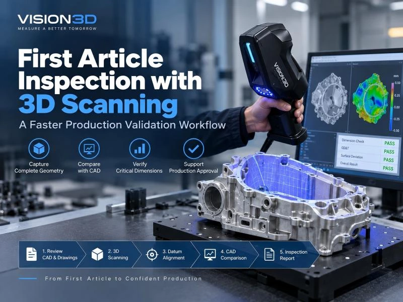
Inspection software compares the scanned model directly with the nominal CAD model, allowing engineers to evaluate dimensional variation across the entire component instead of checking only selected features.
| Inspection Task | Typical Engineering Purpose |
|---|---|
| CAD Deviation Analysis | Visualize dimensional differences across the complete surface. |
| Feature Measurement | Inspect holes, slots, planes, cylinders, and critical dimensions. |
| GD&T Evaluation | Verify geometric tolerances according to engineering drawings. |
| Assembly Verification | Evaluate interfaces, mating surfaces, and assembly conditions. |
| Inspection Reporting | Generate standardized reports for production records and quality traceability. |
Because the inspection data is fully digital, the same dataset can be reviewed repeatedly without rescanning the part. Engineers may perform additional measurements, investigate manufacturing deviations, compare multiple production batches, or share inspection results across quality, manufacturing, and design teams.
Where Blue Light Scanners Deliver the Greatest Value
Blue light scanning is not intended to replace every measurement technology. Instead, it is most valuable when manufacturers need complete surface information, rapid inspection cycles, and reliable digital data for engineering analysis. These requirements are increasingly common across modern production environments where dimensional quality directly affects assembly performance, manufacturing efficiency, and product reliability.
Rather than being limited to a single industry, blue light scanners are widely used wherever complex geometry, freeform surfaces, or high-volume inspection make traditional point-based measurement less efficient.
Automotive Manufacturing
Automotive production relies heavily on dimensional consistency. Components such as Body-in-White structures, stamped panels, battery trays, die castings, and closure systems all require accurate inspection before assembly.
Blue light scanning enables engineers to compare complete parts with CAD models, identify deformation after stamping or welding, inspect hole locations, and evaluate assembly surfaces using full-field measurement rather than isolated sampling.
For automated inspection in automotive production, manufacturers often combine blue structured light technology with robotic measurement systems such as the AutoScan Series to improve inspection consistency and production efficiency.
Precision Manufacturing
Machined housings, tooling components, molds, fixtures, and precision mechanical parts often contain a combination of freeform surfaces and critical geometric features. Blue light scanners provide a practical way to capture complete geometry while allowing engineers to perform dimensional verification, profile inspection, and CAD comparison using a single digital dataset.
Aerospace and Composite Structures
Large composite panels, lightweight structural components, and precision aerospace parts require non-contact measurement methods that avoid mechanical loading while capturing detailed surface geometry. Blue structured light scanning supports inspection throughout manufacturing, tooling verification, and final quality validation.
Although applications vary across industries, the measurement principle remains the same. By converting physical geometry into high-density digital data, blue light scanners provide manufacturers with the information needed to understand dimensional variation, optimize production processes, and improve overall quality control.
Choosing the Right Blue Light Scanning Solution
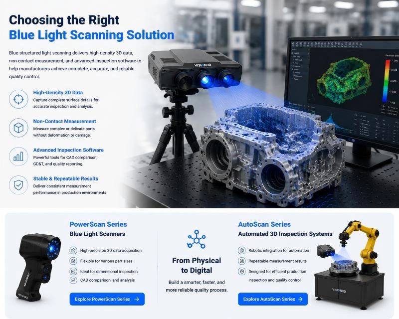
As manufacturing continues to demand higher inspection efficiency, greater measurement coverage, and more reliable digital quality data, blue structured light scanning has become an important technology for modern industrial metrology.
By combining high-density 3D data acquisition, non-contact measurement, and advanced inspection software, blue light scanners enable manufacturers to move beyond traditional point-based measurement and achieve a more complete understanding of part geometry, dimensional variation, and production quality.
However, the best measurement solution depends on the specific application, including component size, surface characteristics, accuracy requirements, inspection workflow, and production environment. Selecting the right scanner configuration and inspection process is essential for achieving stable and repeatable measurement results.
For manufacturers requiring high-precision 3D data acquisition, the PowerScan Series provides blue structured light scanning solutions for detailed dimensional inspection, CAD comparison, and engineering analysis.
For production environments requiring automated and repeatable inspection, the AutoScan Series integrates blue light scanning technology with robotic automation and digital inspection workflows to support efficient quality control.
With the right blue light scanning solution, manufacturers can transform physical components into accurate digital models, improve inspection efficiency, and build a more data-driven quality management process.
For production environments requiring automated and repeatable inspection, the AutoScan Series integrates blue light scanning technology with robotic automation and digital inspection workflows to support efficient quality control.
With the right blue light scanning solution, manufacturers can transform physical components into accurate digital models, improve inspection efficiency, and build a more data-driven quality management process.