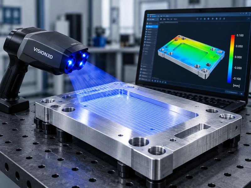
GD&T Symbols and Meanings: A Practical Guide
GD&T symbols are used on engineering drawings to define the allowable variation in a part's geometry. They specify requirements for features such as flatness, perpendicularity, position, and surface profile, helping manufacturers and inspectors determine whether a component meets its design requirements.
Geometric Dimensioning and Tolerancing (GD&T) provides a standardized language for communicating these requirements. Instead of relying only on conventional plus-or-minus dimensions, GD&T defines geometric tolerance zones and, where required, references to datums that establish how a part should be evaluated.
Understanding GD&T symbols and meanings is essential for interpreting technical drawings, planning manufacturing processes, and performing dimensional inspection. Different symbols control different geometric characteristics, and each must be evaluated according to its specified tolerance requirements.
This guide explains the main GD&T symbols, their meanings, and how they are used in engineering drawings. It also examines how 3D scanning and inspection software can support the evaluation of geometric tolerances on manufactured components.
What Is GD&T (Geometric Dimensioning and Tolerancing)?
Geometric Dimensioning and Tolerancing, commonly abbreviated as GD&T, is a system of symbols, rules, and definitions used to specify acceptable geometric variation in manufactured parts.
It is widely applied in mechanical engineering, automotive manufacturing, aerospace, precision machining, and other industries where component geometry affects assembly, function, and interchangeability.
Traditional dimensional tolerances typically control the permitted variation in size or distance. GD&T extends these requirements by defining how individual features must conform to specified geometric conditions.
For example, a machined mounting surface may need to remain sufficiently flat, while a bolt hole must be positioned within a defined tolerance zone relative to specified datum features. These requirements cannot always be communicated adequately through size dimensions alone.
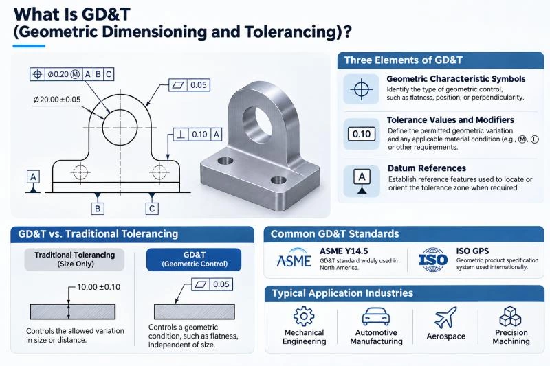
GD&T commonly uses three elements to communicate geometric requirements:
- Geometric characteristic symbols: Identify the type of geometric control, such as flatness, position, or perpendicularity.
- Tolerance values and modifiers: Define the permitted geometric variation and any applicable material condition or other requirements.
- Datum references: Establish reference features used to locate or orient the tolerance zone when required.
GD&T requirements are commonly defined according to standards such as ASME Y14.5 or the applicable ISO GPS standards. Although these systems share many concepts, their interpretation rules are not identical. Engineers should use the standard specified on the drawing rather than assuming that all GD&T conventions are interchangeable.
For quality inspection, understanding the applicable symbols and rules is the first step toward selecting appropriate measurement methods and determining whether a manufactured component satisfies its design requirements.
GD&T Symbols and Their Meanings
GD&T symbols identify the geometric characteristics that must be controlled during manufacturing and inspection. Each symbol represents a specific tolerance requirement, such as maintaining a flat surface, controlling the orientation of a feature, or locating a hole relative to a datum reference frame.
The main GD&T symbols are commonly organized into five categories: form, orientation, location, profile, and runout. Understanding these categories helps engineers interpret drawings and determine which measurement methods are appropriate for each requirement.
The following GD&T symbols chart summarizes the major geometric characteristics and their meanings.
| Category | GD&T Symbol | Characteristic | Meaning |
|---|---|---|---|
| Form | — | Straightness | Controls how much a line element or derived median line may deviate from the specified straightness requirement. |
| Form | ▱ | Flatness | Controls the allowable variation of a surface between two parallel planes. |
| Form | ○ | Circularity | Controls the roundness of individual circular cross-sections. |
| Form | ⌭ | Cylindricity | Controls the overall form of a cylindrical surface within a cylindrical tolerance zone. |
| Orientation | ∥ | Parallelism | Controls the orientation of a feature relative to a specified datum. |
| Orientation | ⟂ | Perpendicularity | Controls how closely a feature maintains a 90-degree orientation relative to a datum. |
| Orientation | ∠ | Angularity | Controls the orientation of a feature at a specified basic angle relative to a datum. |
| Location | ⌖ | Position | Controls the allowable location variation of a feature relative to its theoretically exact position. |
| Profile | ⌒ | Profile of a Line | Controls the allowable variation of a specified cross-sectional profile. |
| Profile | ⌓ | Profile of a Surface | Controls the allowable variation of a three-dimensional surface from its theoretically exact profile. |
| Runout | ↗ | Circular Runout | Controls variation measured at individual circular sections as a part rotates about a datum axis. |
| Runout | ⌰ | Total Runout | Controls the combined variation of a surface over its specified extent relative to a datum axis. |
Note: The characters shown above are simplified text representations of GD&T symbols. Their appearance may vary depending on the font and software. For manufacturing drawings and formal inspection documentation, use standardized symbols from the applicable ASME or ISO standard.
Some older engineering drawings also include concentricity and symmetry controls. These characteristics appeared in earlier editions of ASME Y14.5 but were removed from ASME Y14.5-2018. When interpreting legacy drawings, engineers should verify the specified standard and edition before evaluating these requirements.
Form Tolerances
Form tolerances control the shape of individual features. Straightness, flatness, circularity, and cylindricity are common examples. These controls generally do not require datum references because they evaluate the form of the specified feature itself.
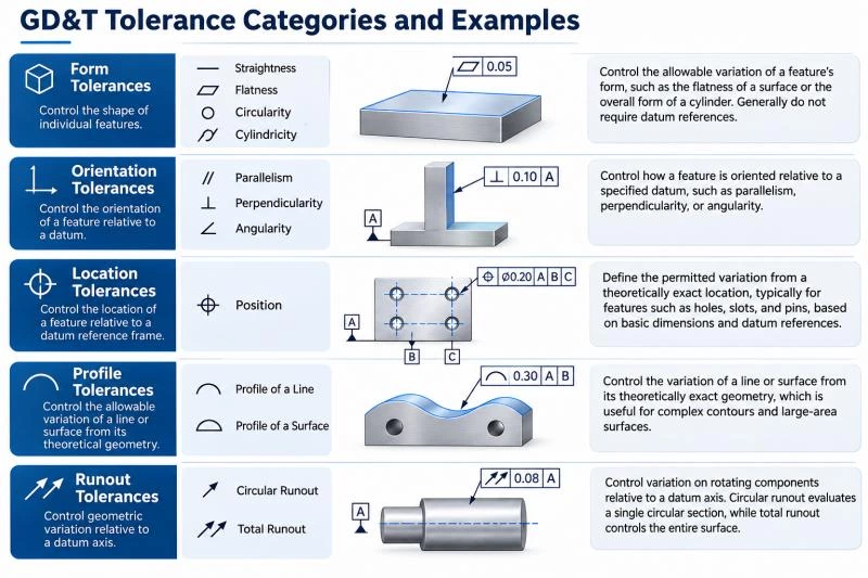
For example, a flatness tolerance defines the maximum permitted separation between two parallel planes that contain the controlled surface. A cylindricity tolerance evaluates the overall form of a cylindrical surface rather than only its individual circular sections.
Orientation Tolerances
Orientation tolerances control how a feature is oriented relative to a specified datum. Parallelism, perpendicularity, and angularity are commonly used to ensure that surfaces, axes, or other features maintain the required geometric relationships.
For example, perpendicularity may be applied to a machined mounting face that must remain perpendicular to a datum surface. The tolerance defines an allowable zone rather than simply specifying an angular deviation in degrees.
Location Tolerances
Position is one of the most widely used GD&T controls for locating features such as holes, slots, and pins. It defines the permitted variation from a theoretically exact location established by basic dimensions and applicable datum references.
For a hole, a position tolerance may define a cylindrical zone within which the derived axis must lie. The exact evaluation depends on the feature control frame, applicable modifiers, and drawing standard.
Profile Tolerances
Profile tolerances control the allowable variation of a line or surface from its theoretically exact geometry. They are particularly useful for components with complex contours that cannot be adequately controlled using simple size or orientation tolerances.
Profile of a line applies to specified cross-sectional geometry, while profile of a surface controls a three-dimensional surface. Depending on the drawing requirements, profile controls may regulate form alone or combine form with orientation and location.
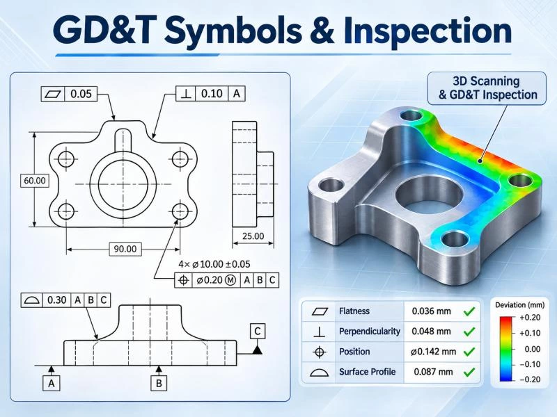
For complex manufactured components, surface profile evaluation is an important application of 3D measurement data because it may require checking geometric deviations across a large number of surface locations.
Runout Tolerances
Runout tolerances are commonly applied to rotating components such as shafts and cylindrical surfaces. They control geometric variation relative to a datum axis.
Circular runout evaluates variation at individual circular sections, while total runout evaluates the controlled surface over its specified extent. These requirements are particularly relevant when rotational accuracy and assembly performance are important.
Although the GD&T symbols chart provides a useful reference, a symbol alone does not fully define an inspection requirement. The tolerance value, datum references, modifiers, and applicable drawing standard must also be considered before determining how a feature should be measured.
Understanding GD&T Feature Control Frames
Knowing the meanings of GD&T symbols is only the first step in interpreting an engineering drawing. To understand the complete tolerance requirement, engineers must also read the feature control frame, which specifies how a geometric characteristic is controlled and which references or modifiers apply.
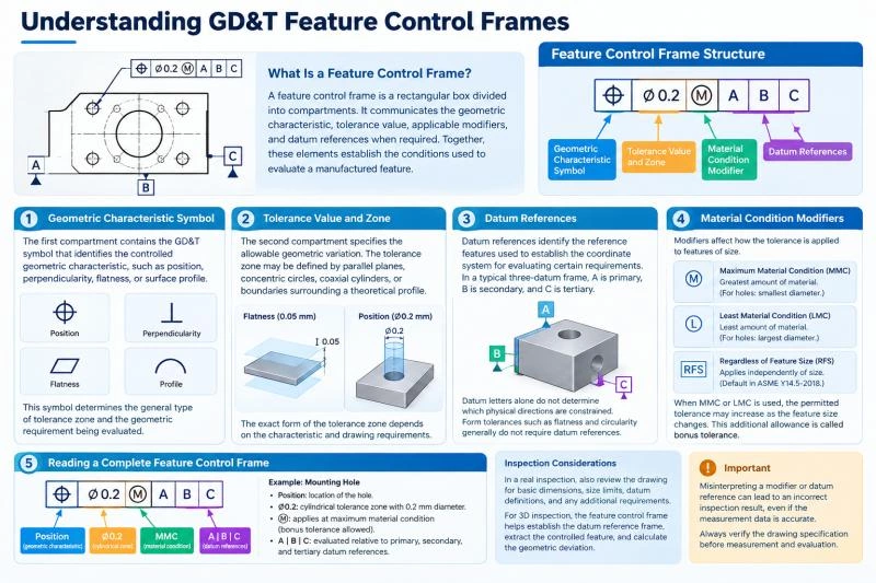
A feature control frame is a rectangular box divided into compartments. It communicates the geometric characteristic, tolerance value, applicable modifiers, and datum references when required. Together, these elements establish the conditions used to evaluate a manufactured feature.
For example, a position tolerance applied to a mounting hole may specify a cylindrical tolerance zone of 0.2 mm relative to datums A, B, and C. The position symbol identifies the geometric characteristic, while the remaining information defines how the hole's location is evaluated.
1. Geometric Characteristic Symbol
The first compartment contains the GD&T symbol that identifies the controlled geometric characteristic, such as position, perpendicularity, flatness, or surface profile.
This symbol determines the general type of tolerance zone and the geometric requirement being evaluated. However, the symbol must be interpreted together with the remaining information in the feature control frame.
2. Tolerance Value and Zone
The second compartment specifies the allowable geometric variation. Depending on the characteristic and drawing requirements, the tolerance zone may be defined by parallel planes, concentric circles, coaxial cylinders, or boundaries surrounding a theoretically exact profile.
For instance, a flatness tolerance of 0.05 mm requires the controlled surface to lie between two parallel planes separated by 0.05 mm.
For a position tolerance applied to a hole axis, the diameter symbol (⌀) before the tolerance value indicates a cylindrical tolerance zone. A specification of ⌀0.2 establishes a cylindrical zone with a diameter of 0.2 mm.
3. Datum References
Datum references identify the reference features used to establish the coordinate system for evaluating certain geometric requirements.
When multiple datums are specified, their sequence is important. In a typical three-datum reference frame, datum A serves as the primary reference, datum B as the secondary reference, and datum C as the tertiary reference.
The datum reference frame constrains the relevant degrees of freedom according to the applicable drawing standard and the geometry of the referenced datum features. The letters alone do not determine which physical directions are constrained.
Not every GD&T tolerance requires a datum reference. Form tolerances such as flatness and circularity generally control individual features independently of a datum reference frame.
4. Material Condition Modifiers
Some GD&T requirements include material condition modifiers that affect how the specified tolerance is applied to features of size.
- Maximum Material Condition (MMC), Ⓜ: Refers to the size condition at which a feature contains the greatest amount of material. For an internal feature such as a hole, this is its smallest permitted diameter.
- Least Material Condition (LMC), Ⓛ: Refers to the size condition at which a feature contains the least amount of material. For a hole, this is its largest permitted diameter.
- Regardless of Feature Size (RFS): Indicates that the geometric tolerance applies independently of the actual feature size. Under ASME Y14.5-2018, RFS is the default unless otherwise specified where applicable.
When MMC or LMC is applied to an eligible geometric tolerance, the permitted geometric variation may change as the actual feature size departs from the specified material condition. This additional allowance is commonly called bonus tolerance.
For example, consider a hole with a diameter range of 10.0–10.2 mm and a position tolerance of ⌀0.2 mm at MMC. The hole's MMC size is 10.0 mm. If its actual mating-envelope size is 10.1 mm, the available bonus tolerance is 0.1 mm, giving a total position tolerance of ⌀0.3 mm, assuming the applicable ASME rules and no other restrictions.
This is why dimensional inspection must consider both the measured feature size and the geometric requirement when a material condition modifier applies.
5. Reading a Complete Feature Control Frame
Consider the following example for a mounting hole:
Position | ⌀0.2 Ⓜ | A | B | C
This requirement can be interpreted as follows:
- Position: The controlled characteristic is the location of the hole.
- ⌀0.2: The specified positional tolerance zone is cylindrical, with a diameter of 0.2 mm at the stated material condition.
- Ⓜ: The tolerance applies at maximum material condition, allowing bonus tolerance where the applicable rules permit.
- A | B | C: The feature is evaluated relative to the specified primary, secondary, and tertiary datum references.
In a real inspection, the complete drawing must also be reviewed to identify the hole's basic dimensions, size limits, datum feature definitions, and any additional requirements.
For 3D inspection, the feature control frame provides the basis for establishing the correct datum reference frame, extracting the controlled feature from measurement data, and calculating the relevant geometric deviation.
Misinterpreting a modifier or datum reference can produce an incorrect inspection result even when the underlying measurement data is accurate. Therefore, the drawing specification must be verified before the measurement and tolerance evaluation process begins.
Which GD&T Tolerances Can Be Measured with 3D Scanning?
Many GD&T symbols describe geometric characteristics that can be evaluated using three-dimensional measurement data. However, not every geometric tolerance is equally suitable for optical 3D scanning. The feasibility of an inspection depends on the controlled feature, tolerance requirements, surface accessibility, measurement uncertainty, and applicable drawing standard.
Optical 3D scanners capture the visible geometry of a component and generate measurement data that can be analyzed using inspection software. For GD&T inspection, this data may be used to extract geometric features, establish datum reference frames, and evaluate deviations against specified tolerance zones.
The following table summarizes common GD&T tolerances and their potential applications in 3D scanning inspection.
| GD&T Characteristic | 3D Scanning Applicability | Typical Inspection Application | Key Consideration |
|---|---|---|---|
| Flatness | Often suitable | Machined plates, mounting surfaces, large panels | Surface coverage, measurement uncertainty, and fitting method |
| Straightness | Conditionally suitable | Accessible edges and surface line elements | Derived median-line controls may require additional measurements |
| Circularity | Conditionally suitable | Accessible cylindrical cross-sections | Complete circumferential coverage and sufficient accuracy |
| Cylindricity | Conditionally suitable | External cylindrical surfaces | Full surface coverage and appropriate feature evaluation |
| Parallelism | Often suitable | Opposing surfaces and parallel mounting features | Correct datum establishment |
| Perpendicularity | Often suitable | Machined faces, brackets, accessible cylindrical features | Feature extraction and datum alignment |
| Angularity | Often suitable | Inclined mounting faces and angled structural features | Basic angle and datum requirements |
| Position | Conditionally suitable | Accessible holes, slots, bosses, and mounting features | Feature size, axis extraction, and material condition modifiers |
| Profile of a Line | Often suitable | Specified cross-sectional contours | Correct section definition and tolerance-zone interpretation |
| Profile of a Surface | Often suitable | Castings, stampings, molded parts, complex surfaces | Datum requirements, coverage, and uncertainty |
| Circular Runout | Limited or conditional | Accessible rotational surfaces | Correct datum axis and section-by-section evaluation |
| Total Runout | Limited or conditional | External cylindrical or rotational surfaces | Surface coverage and evaluation relative to the datum axis |
Note: These classifications indicate potential measurement suitability, not guaranteed inspection capability. A specific tolerance can only be evaluated reliably when the measurement system, inspection procedure, and uncertainty are appropriate for the drawing requirements.
Surface Profile Inspection
Surface profile is one of the most practical applications of 3D scanning in geometric inspection. It is commonly specified for components with curved, freeform, or complex surfaces, including automotive stampings, castings, and molded parts.
A 3D scanner can capture numerous points across an accessible surface, allowing inspection software to evaluate deviations from the theoretically exact geometry.
However, a color deviation map alone does not establish GD&T conformance. The software must apply the correct profile tolerance zone, datum reference frame, and any specified unequal or otherwise modified profile requirements.
Form and Orientation Inspection
Optical 3D measurement can also support the evaluation of form and orientation characteristics such as flatness, parallelism, perpendicularity, and angularity.
For example, a scanned mounting bracket may contain several accessible planar surfaces. Inspection software can extract these features and evaluate their geometric relationships according to the drawing.
The evaluation method must match the specified characteristic. A least-squares fitted plane may be useful for feature construction, but its residuals or angular relationship do not automatically represent the required GD&T tolerance result.
Measurement uncertainty becomes particularly important when inspecting tightly controlled surfaces. Scanner noise, incomplete coverage, filtering, and feature fitting can affect the reported deviation.
Position Inspection of Holes and Mounting Features
Position tolerances are frequently applied to holes, slots, pins, and other assembly features. Optical 3D scanning can support position inspection when sufficient geometry is accessible to construct the controlled feature accurately.
For a mounting hole, scanning only the visible rim may provide information about its opening, but it may not provide enough data to establish the actual hole axis or evaluate a position tolerance applied to the full feature of size.
Where internal geometry is inaccessible, supplementary measurements may be necessary. The inspection method must also account for applicable material condition modifiers and the feature's actual size.
For components containing many accessible mounting features, 3D scanning may contribute to a broader dimensional inspection workflow, provided each feature can be evaluated according to the drawing requirements.
Runout Inspection
Circular runout and total runout require particular care because their tolerance definitions are related to a specified datum axis and the controlled surface's behavior relative to that axis.
A complete 3D surface dataset may support certain computational runout evaluations when the datum axis and controlled geometry are properly established. However, a static surface scan does not directly reproduce a conventional rotational runout measurement.
For precision shafts, bearings, and other rotational components, dedicated rotational measurement equipment or contact-based methods may be more appropriate, depending on the tolerance and inspection requirements.
GD&T Requirements That Optical Scanning Cannot Fully Evaluate
Optical 3D scanning is fundamentally limited by line-of-sight access and the characteristics of the measurement system. Deep internal bores, hidden surfaces, enclosed passages, and other inaccessible features cannot generally be captured directly by conventional external optical scanning.
Some GD&T requirements also depend on feature-of-size measurements, derived axes, mating envelopes, or specialized evaluation rules that cannot be established reliably from incomplete surface data.
In these situations, inspection may require complementary technologies such as coordinate measuring machines, bore gauges, roundness measuring instruments, or industrial computed tomography.
The appropriate method should be selected according to the specific geometric requirement rather than the GD&T symbol alone.
For manufacturers using industrial 3D measurement systems, the practical objective is not to replace every inspection method with scanning. It is to identify which geometric characteristics can be evaluated reliably from optical measurement data and integrate those results into a consistent dimensional quality control process.
Why Datum Alignment Matters in GD&T Inspection
Datum alignment plays an important role in GD&T inspection because it establishes the reference conditions used to evaluate the location and orientation of controlled features. Even when the same measurement data is used, different alignment methods can produce different geometric deviation results.
For GD&T requirements involving datum references, the inspection alignment must reflect the datum reference frame specified on the engineering drawing. An arbitrary coordinate system or unrestricted CAD best-fit alignment may not represent the required inspection conditions.
Understanding this distinction is particularly important when evaluating position, perpendicularity, angularity, and surface profile tolerances.
Datum-Based Alignment vs. Best-Fit Alignment
Best-fit alignment adjusts the position and orientation of measured geometry to reduce deviations between the measurement data and a reference model. It is useful for certain dimensional analysis tasks, but its optimization criteria do not necessarily correspond to the datum requirements specified in a GD&T feature control frame.
Datum-based alignment establishes the reference frame using the designated datum features and their specified order of precedence. Depending on the drawing, this may involve planar surfaces, cylindrical features, slots, or other geometric elements.
The difference becomes important when a component contains manufacturing deviations. A best-fit alignment may distribute these deviations across multiple surfaces, while datum-based alignment preserves the relationships required for evaluating controlled features.
Example: Position Inspection of a Mounting Hole
Consider a machined bracket with three datum features and a mounting hole controlled by the following position tolerance:
Position | ⌀0.20 | A | B | C
The engineering drawing defines the hole's theoretically exact location using basic dimensions relative to datum reference frame A-B-C.
Assume that, after establishing the correct datum reference frame, the measured hole axis is parallel to the nominal axis and has the following transverse offsets:
- X-direction offset: 0.08 mm
- Y-direction offset: 0.06 mm
For this simplified example, the radial offset of the measured axis is:
Radial offset = √(0.08² + 0.06²) = 0.10 mm
Because the position tolerance is specified as a diametrical zone, the corresponding positional deviation is:
Positional deviation = 2 × 0.10 = 0.20 mm
The result is exactly at the specified positional tolerance limit of ⌀0.20 mm.
This calculation assumes a straight measured axis parallel to the nominal axis, no applicable material condition modifier, and no additional evaluation requirements. For an actual feature, axis orientation, feature extent, and the applicable GD&T rules must also be considered.
If the same scan data were aligned using an unrestricted best-fit method, the reported X and Y offsets could change because the measured component would be repositioned relative to the CAD model.
Such a result would not necessarily represent the position tolerance relative to the required datum reference frame.
Datum Establishment for Complex Parts
For complex castings, automotive components, and machined assemblies, datum establishment may involve multiple surfaces or features with manufacturing variation.
The inspection procedure must identify the correct datum features and apply the appropriate datum simulation or construction rules. A nominal CAD plane or axis should not automatically be treated as equivalent to a datum established from the actual part.
In addition, datum feature modifiers may permit controlled movement of the datum reference frame under certain conditions. These requirements must be interpreted according to the applicable drawing standard.
When using 3D scan data, the measurement system must capture sufficient geometry to support the required datum construction. If critical datum features are inaccessible or cannot be measured with adequate uncertainty, supplementary measurement methods may be necessary.
Correct datum establishment helps ensure that the final GD&T inspection result reflects the functional geometric relationships specified by the designer rather than an arbitrary alignment of the measured part.
Common Mistakes in GD&T Inspection
GD&T inspection errors do not always originate from inaccurate measurement equipment. They can also result from incorrect drawing interpretation, inappropriate feature construction, or applying evaluation methods that do not match the specified geometric requirement.
The following mistakes are particularly important when using 3D scanning for dimensional inspection.
1. Interpreting GD&T Symbols Without Reading the Complete Feature Control Frame
A GD&T symbol identifies the geometric characteristic being controlled, but it does not independently define the complete inspection requirement.
For example, a position symbol must be interpreted together with its tolerance value, applicable modifiers, basic dimensions, and datum references.
Ignoring these elements may result in evaluating the correct feature against the wrong tolerance conditions.
2. Using Best-Fit Alignment Instead of the Required Datum Reference Frame
Best-fit alignment can reduce overall CAD-to-scan deviations, but it may change the apparent location or orientation of individual features.
When a tolerance references datums, the inspection must establish the required datum reference frame rather than automatically using a global best-fit alignment.
3. Confusing Surface Deviation with GD&T Tolerance Results
A color deviation map shows differences between measured geometry and a reference surface under a particular alignment and comparison method.
However, these deviations do not necessarily represent flatness, position, profile, or other GD&T results.
Each characteristic requires evaluation against its defined tolerance zone. A surface may show small CAD deviations while still failing a particular geometric requirement, or it may display larger deviations without violating the specified tolerance, depending on the evaluation conditions.
4. Extracting Features from Incomplete Scan Data
Optical scanning measures visible surfaces. When only part of a controlled feature is captured, the resulting geometric construction may not adequately represent the complete feature.
For example, a hole axis constructed from a limited portion of its opening may differ from an axis established using sufficient internal cylindrical geometry.
Before performing GD&T inspection, engineers should confirm that the captured data supports the required feature definition and evaluation method.
5. Ignoring Material Condition Modifiers
Material condition modifiers can affect the allowable geometric tolerance for eligible features of size.
If a position tolerance is specified at MMC, the permitted positional variation may increase as the feature departs from its maximum material condition.
Evaluating the feature using only the stated geometric tolerance value, without considering the applicable size-dependent allowance, may lead to an incorrect conformity decision.
6. Applying an Incorrect Feature-Fitting Method
Geometric feature construction can involve different fitting and association methods, including least-squares and minimum-zone approaches.
These methods do not necessarily produce identical results. A fitting method suitable for establishing a nominal feature may not be appropriate for calculating a particular GD&T characteristic.
For example, the maximum residual from a least-squares plane is not automatically equivalent to a correctly evaluated flatness result.
The inspection procedure should use the evaluation method required by the applicable standard and measurement specification.
7. Overlooking Measurement Uncertainty
A numerical result displayed by inspection software is not sufficient evidence of conformance when the measurement uncertainty is unsuitable for the tolerance being evaluated.
Measurement uncertainty may be influenced by scanner performance, calibration, surface properties, environmental conditions, feature extraction, and data processing.
For tightly controlled features, manufacturers should establish an appropriate measurement capability and decision rule before accepting or rejecting parts.
A consistent GD&T inspection procedure should therefore combine correct drawing interpretation, suitable measurement data, standard-compliant evaluation methods, and documented quality requirements.
Frequently Asked Questions About GD&T Symbols and Inspection
What are the main categories of GD&T symbols?
GD&T symbols are commonly grouped into five categories: form, orientation, location, profile, and runout. These categories describe different geometric characteristics, including flatness, perpendicularity, position, surface profile, and circular runout. The exact symbols and interpretation rules depend on the applicable drawing standard.
What is the difference between GD&T and traditional dimensional tolerancing?
Traditional dimensional tolerancing generally specifies allowable variations in sizes and distances. GD&T provides additional controls for geometric characteristics such as form, orientation, location, and profile. It uses defined tolerance zones and, where required, datum reference frames to communicate functional geometric requirements.
Do all GD&T symbols require datum references?
No. Form tolerances such as flatness, circularity, and cylindricity generally do not require datum references. Orientation and runout tolerances typically use datums, while position and profile controls may involve datum references depending on the specified requirement and applicable standard.
What does the position symbol mean in GD&T?
The position symbol indicates a geometric tolerance that controls the allowable location variation of a feature from its theoretically exact position. For a cylindrical feature of size, the tolerance may define a cylindrical zone within which the derived axis must lie, subject to the applicable modifiers and evaluation rules.
What is the difference between MMC and LMC in GD&T?
Maximum Material Condition (MMC) refers to the size condition at which a feature contains the greatest amount of material. Least Material Condition (LMC) refers to the condition at which it contains the least material. For a hole, MMC corresponds to the smallest permitted diameter, while LMC corresponds to the largest permitted diameter. These modifiers can affect geometric tolerance evaluation when applicable.
Can a 3D scanner measure GD&T tolerances?
Yes. Optical 3D scanning can support the evaluation of several GD&T characteristics, including surface profile, flatness, orientation, and certain position tolerances. However, suitability depends on feature accessibility, required measurement uncertainty, data coverage, and the evaluation capabilities of the inspection software. Some requirements need supplementary measurement methods.
Can GD&T inspection be performed directly from a point cloud?
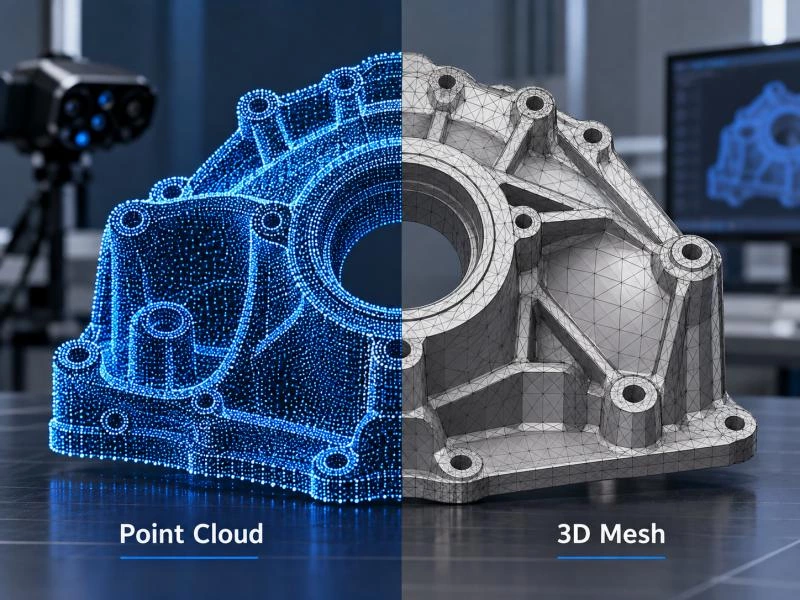
Measured point cloud data can be used as input for GD&T inspection, but the data must be processed and evaluated according to the specified geometric requirements. This may involve datum construction, feature extraction, tolerance-zone calculation, and application of relevant modifiers. A basic point cloud-to-CAD deviation comparison is not sufficient for every GD&T characteristic.
Which GD&T standard should be used for inspection?
Inspection should follow the standard and edition specified on the engineering drawing, such as ASME Y14.5 or the relevant ISO GPS standards. These systems have differences in terminology, rules, and interpretation. The inspection procedure should not combine requirements from different standards without an appropriate technical basis.
Conclusion
Understanding GD&T symbols and meanings is essential for interpreting engineering drawings and evaluating the geometric quality of manufactured components. Each symbol defines a particular geometric characteristic, but a complete inspection requires consideration of tolerance values, datum references, modifiers, and the applicable standard.
For industrial dimensional inspection, 3D scanning provides a practical way to capture accessible surface geometry and support the evaluation of selected geometric tolerances. Surface profile, form, orientation, and certain location requirements can be assessed using suitable measurement data and inspection software.
However, reliable GD&T inspection depends on more than measurement coverage. Correct datum establishment, feature extraction, tolerance-zone interpretation, and measurement uncertainty are necessary to obtain meaningful results.
VISION3D provides industrial 3D measurement solutions for manufacturers working with complex components and dimensional quality control requirements. Explore the PowerScan Series for blue light 3D scanning, the AutoScan Series for automated measurement applications, and VisionInspect for 3D inspection software.
For specific geometric inspection requirements, contact the VISION3D team to discuss component geometry, tolerance specifications, and suitable measurement approaches.