How to Measure Flatness with a 3D Scanner
Flatness is an important geometric requirement in industrial manufacturing, particularly for machined surfaces, mounting interfaces, castings, and precision components. Even when a part meets its dimensional specifications, surface irregularities can affect assembly fit, sealing performance, and mechanical stability.
Measuring flatness with a 3D scanner allows engineers to capture surface geometry and evaluate deviations across a large number of measured points. Unlike inspection methods that examine only selected locations, optical 3D scanning can provide broader surface coverage, helping quality teams identify localized deformation, unevenness, and manufacturing variation.
However, obtaining a point cloud is only the beginning. Reliable flatness inspection also depends on surface preparation, measurement conditions, data processing, plane fitting, and the evaluation method used to calculate flatness.
This guide explains how to measure flatness with a 3D scanner, how flatness is calculated from 3D measurement data, and what engineers should consider when interpreting inspection results.
What Is Flatness in Dimensional Inspection?
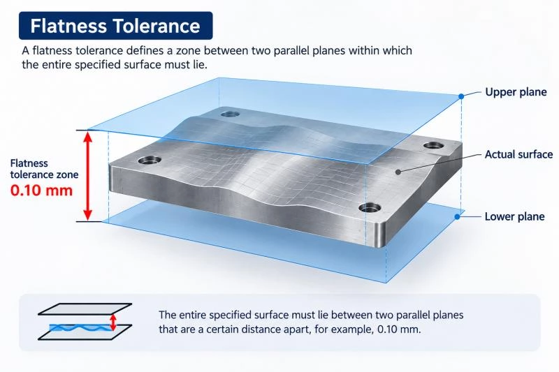
Flatness is a geometric form tolerance that controls how much a surface can deviate from an ideal plane. In geometric dimensioning and tolerancing (GD&T), a flatness tolerance defines a zone between two parallel planes within which the entire specified surface must lie.
For example, if a drawing specifies a flatness tolerance of 0.10 mm, the measured surface must fit between two parallel planes separated by no more than 0.10 mm, using the applicable evaluation rules.
Unlike parallelism or perpendicularity, flatness is a form tolerance and does not require an external datum reference. It evaluates the surface's own geometric variation rather than its orientation relative to another feature.
Why Flatness Matters in Manufacturing
Flatness deviations can affect both product performance and downstream assembly. The importance of flatness depends on the component's function, material, manufacturing process, and specified tolerances.
| Application | Why Flatness Matters | Potential Quality Issue |
|---|---|---|
| Machined mounting surfaces | Supports stable contact between assembled components | Uneven seating or assembly misalignment |
| Sealing interfaces | Helps maintain consistent contact with gaskets or mating surfaces | Localized gaps or sealing problems |
| Cast and forged components | Identifies deformation and uneven surfaces before machining or assembly | Insufficient machining allowance or poor fit |
| Thin-walled components | Helps evaluate distortion caused by forming, machining, or thermal processes | Warpage and inconsistent assembly geometry |
Flatness inspection is therefore not simply about determining whether a surface looks smooth. It provides measurable geometric information that engineers can use to verify tolerances, investigate manufacturing variation, and support quality decisions.
Can a 3D Scanner Measure Flatness?
Yes, a 3D scanner can be used to measure flatness by capturing the three-dimensional coordinates of points across a surface and evaluating their deviation from an ideal plane. Optical 3D scanning is particularly useful when engineers need to examine surface variation across a relatively large area or identify localized deformation that may be missed by limited point measurements.
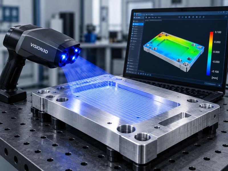
Industrial structured-light scanners project a pattern of light onto the workpiece and use cameras to reconstruct its surface geometry. The resulting point cloud provides spatial data that inspection software can process for geometric evaluation.
For example, an industrial blue-light 3D scanner can capture accessible surfaces of machined components, castings, and structural parts for subsequent dimensional analysis. Whether the resulting data is suitable for a particular flatness tolerance depends on the scanner's verified measurement performance, the inspection setup, and the evaluation method.
However, not every flatness inspection task is suitable for optical scanning. Highly reflective surfaces, deep recesses, limited optical access, and extremely tight tolerances may require additional preparation or alternative measurement methods.
| Inspection Condition | Suitability for 3D Scanning | Key Consideration |
|---|---|---|
| Large accessible surfaces | Generally suitable | Measurement volume and surface coverage |
| Complex cast or machined parts | Suitable when the target surface is visible | Occlusion, alignment, and local surface detail |
| Thin or flexible components | Conditionally suitable | Fixture-induced deformation and part support |
| Highly reflective or transparent surfaces | May require special preparation | Optical measurement noise and missing data |
| Very tight flatness tolerances | Requires measurement capability verification | Measurement uncertainty relative to tolerance |
Before selecting a 3D scanner for flatness inspection, engineers should confirm that the measurement system can resolve the expected surface variation with sufficient confidence for the specified tolerance.
How to Measure Flatness with a 3D Scanner
A reliable 3D flatness measurement process involves more than scanning a surface and reading a deviation value. The inspection procedure must control how the part is positioned, how surface data is captured, and how the measured points are evaluated.
The following workflow outlines the main steps used in industrial optical flatness inspection.
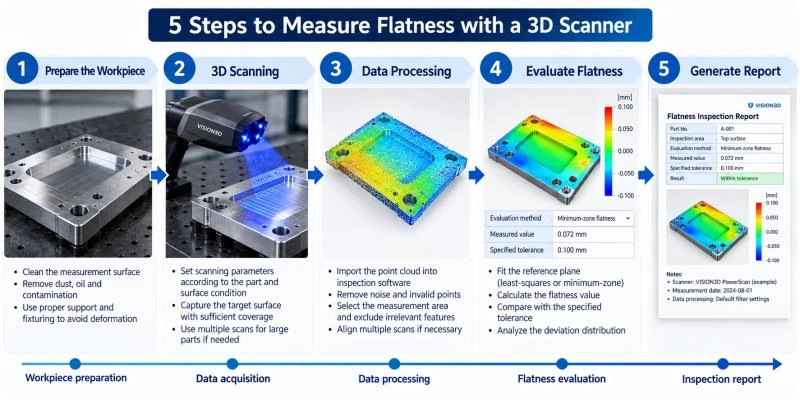
Step 1: Review the Flatness Requirement
Start by identifying the surface controlled by the flatness specification and the applicable drawing requirements. Confirm the tolerance value, inspection area, relevant manufacturing standard, and whether any portion of the surface is excluded from evaluation.
For example, a flatness tolerance of 0.10 mm defines the permitted form variation of the specified surface. The inspection method must provide adequate measurement capability to determine whether the actual surface meets that requirement.
It is also important to distinguish flatness from related characteristics such as parallelism, surface profile, and surface roughness. These characteristics describe different geometric requirements and may require different evaluation methods.
Step 2: Prepare and Position the Workpiece
Clean the measurement surface to remove dust, oil, loose particles, or other contamination that could influence the captured geometry. Depending on the optical properties of the material, additional surface preparation may be necessary.
Position the workpiece so the target surface is accessible to the scanner. The support method should reflect the intended inspection condition, particularly for thin-walled or flexible components that may deform under their own weight or under clamping forces.
A rigid part may be measured on a stable fixture, while a flexible component may require a defined support arrangement. Excessive clamping can change the surface geometry and produce a result that does not represent the intended condition of the part.
Step 3: Capture the Surface with a 3D Scanner
Configure the scanner according to the measurement volume, surface properties, and required level of detail. Capture the specified surface with sufficient coverage while avoiding unnecessary changes in scanner position or workpiece setup.
For larger components, multiple scans may be required. These scans must be registered into a consistent coordinate system before evaluation. Registration quality should be checked because errors between scan positions can introduce artificial surface variation.
Engineers should also inspect the acquired data for missing regions, reflections, excessive noise, or other artifacts. A visually complete point cloud does not automatically guarantee reliable measurement data.
Step 4: Process and Select the Measurement Data
Import the captured point cloud or surface mesh into suitable metrology software. Identify the surface region corresponding to the flatness requirement and exclude unrelated features such as holes, edges, neighboring faces, or fixture geometry.
Data filtering may be necessary to remove clearly invalid measurements. However, excessive smoothing or aggressive outlier removal can suppress genuine surface peaks and valleys, leading to an underestimated flatness result.
The data selection and filtering rules should therefore be documented and applied consistently. Measurement points should represent the specified surface rather than an artificially smoothed version of it.
Step 5: Establish the Evaluation Plane
The inspection software evaluates the measured surface relative to an ideal plane. A least-squares plane is often used as an initial fitted reference because it minimizes the sum of squared point-to-plane distances.
However, the least-squares plane is not necessarily the plane orientation that produces the minimum flatness zone. When the inspection specification requires minimum-zone flatness evaluation, the software must determine the smallest separation between two parallel planes that enclose the evaluated surface data.
Engineers should verify which fitting and evaluation algorithms the software uses rather than assuming that all reported plane deviations represent the same flatness characteristic.
Step 6: Evaluate Flatness and Generate the Inspection Report
Calculate the flatness value using the specified evaluation method and compare the result with the drawing tolerance. The report should identify the inspected surface, evaluation method, measured flatness, tolerance, and relevant measurement conditions.
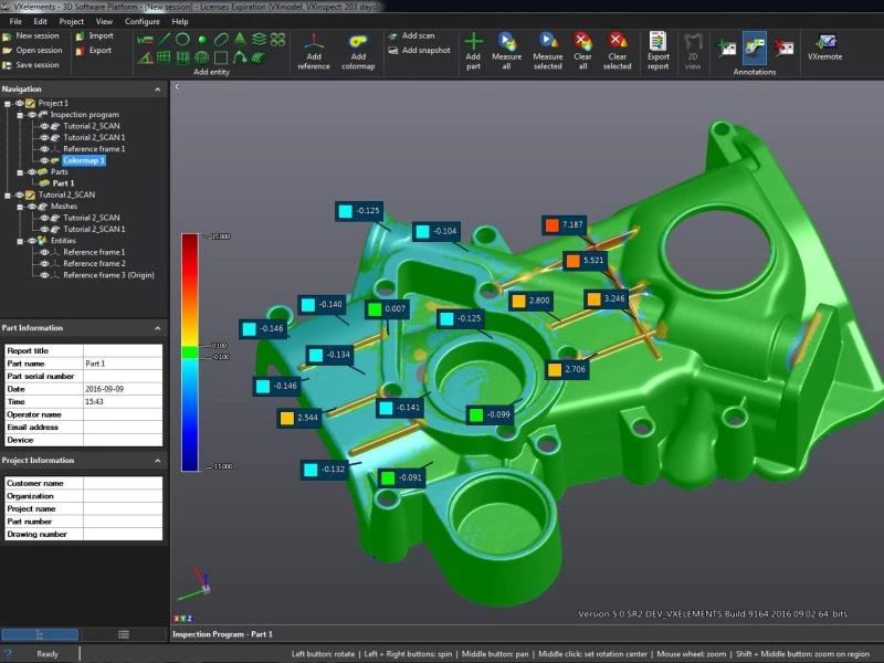
A surface deviation map can help engineers locate high and low regions, while numerical results provide the basis for tolerance evaluation. Where supported, inspection software can also document the measurement data and generate standardized reports for quality records.
For production quality control, consistent scanning procedures and evaluation settings are essential when comparing results across different parts, operators, or inspection periods.
How Is Flatness Calculated from 3D Scan Data?
Flatness measurement evaluates the geometric variation of a surface relative to an ideal plane. After a 3D scanner captures the surface, inspection software analyzes the measured points to determine how closely the actual geometry conforms to the specified flatness tolerance.
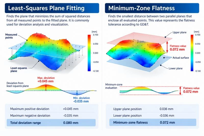
However, the calculated result depends on the evaluation method. Least-squares plane fitting and minimum-zone flatness evaluation are commonly discussed in dimensional metrology, but they do not necessarily produce the same value.
Least-Squares Plane Fitting
A least-squares plane is calculated by finding the plane that minimizes the sum of squared perpendicular distances from the measured surface points. It provides a useful reference for visualizing surface variation and analyzing the distribution of measurement deviations.
Once the plane is established, the software can calculate the signed distance of each measured point from that plane. The difference between the largest positive and largest negative deviations represents the total point-to-plane deviation range for that particular fitted plane.
For example, consider a measured surface with the following deviations from its least-squares plane:
| Measurement Result | Example Value |
|---|---|
| Maximum positive deviation | +0.045 mm |
| Maximum negative deviation | -0.035 mm |
| Total deviation range | 0.080 mm |
In this example, the measured points have a total deviation range of 0.080 mm relative to the least-squares plane. This value describes the spread of the selected points for that fitted plane, but it should not automatically be reported as minimum-zone flatness.
Minimum-Zone Flatness Evaluation
Minimum-zone evaluation determines the smallest distance between two parallel planes that can enclose the evaluated surface data. The orientation of the planes is adjusted to minimize their separation while containing the measured points.
This approach reflects the geometric definition of a flatness tolerance zone. Depending on the surface geometry, the minimum-zone result may be smaller than the deviation range calculated from a least-squares plane.
For reliable inspection, engineers should confirm whether their software reports least-squares deviation, minimum-zone flatness, or another result defined by the applicable specification.
Why the Evaluation Method Matters
Two inspection systems can analyze the same point cloud and produce different numerical results if they use different fitting methods, data selection rules, or filtering settings. These differences do not necessarily indicate that one scanner captured the surface incorrectly.
The measurement procedure should therefore define the evaluation method, selected surface region, filtering rules, and relevant inspection settings before results are compared or used for acceptance decisions.
What Affects Flatness Measurement Accuracy?
Accurate flatness inspection requires more than a high-resolution point cloud. The measurement result is influenced by the scanner, workpiece, environment, data processing, and evaluation procedure. Understanding these factors helps engineers determine whether optical 3D scanning is suitable for a particular flatness tolerance.
1. Scanner Calibration and Measurement Performance
Scanner calibration establishes the relationship between captured image information and reconstructed three-dimensional coordinates. Calibration condition, measurement volume, scanner configuration, and system stability can influence the quality of the acquired surface data.
When selecting an industrial 3D scanner for flatness inspection, engineers should examine verified measurement performance under relevant operating conditions rather than relying only on point spacing or nominal resolution.
A scanner that captures very dense data is not necessarily capable of evaluating extremely small flatness tolerances. Measurement uncertainty must be considered in relation to the required tolerance and the organization's acceptance rules.
2. Surface Reflectivity and Optical Properties
Highly reflective, transparent, dark, or optically inconsistent surfaces may introduce missing points or measurement noise. Reflections and unstable image contrast can affect the reconstruction of the measured surface.
Suitable scanning parameters, controlled lighting, and approved surface preparation methods may improve data acquisition. However, applying a scanning spray introduces an additional surface layer that may influence the measured geometry, particularly when the flatness tolerance is very small.
Engineers should evaluate whether surface treatment is acceptable for the part and whether its potential influence is significant relative to the inspection requirement.
3. Workpiece Positioning and Fixture Stability
Flatness measurement is sensitive to the physical condition of the workpiece during inspection. Thin plates, flexible components, and large structures may deform under their own weight or when clamped into a fixture.
If the inspection setup forces a distorted component into a flatter condition, the resulting measurement may not represent its intended free-state geometry. Conversely, insufficient support may introduce deformation unrelated to the manufacturing process.
The inspection procedure should specify the required support and restraint conditions, especially for components whose geometry changes significantly with orientation or clamping force.
4. Point Cloud Coverage and Registration
Optical scanning requires sufficient visibility of the target surface. Missing regions, excessive measurement noise, or poor coverage can affect the reliability of flatness evaluation.
For large surfaces captured through multiple scans, registration errors may introduce artificial steps or curvature into the combined point cloud. These errors can be difficult to distinguish from actual surface deformation if the alignment process is not verified.
Where possible, engineers should minimize unnecessary scan registration and validate the consistency of overlapping measurement regions.
5. Data Filtering and Surface Processing
Inspection software may provide noise reduction, outlier removal, mesh generation, and surface smoothing tools. These functions can improve data usability, but they must be applied carefully during dimensional inspection.
Removing points near genuine surface peaks or valleys can reduce the calculated deviation range. Similarly, excessive smoothing may hide localized deformation and produce a result that appears better than the actual surface condition.
Filtering methods should be documented, justified, and applied consistently. Engineers should retain access to the original measurement data when investigating unexpected results.
6. Temperature and Environmental Conditions
Temperature changes can affect the dimensions and shape of both the workpiece and the measurement setup. Thermal expansion, temperature gradients, vibration, and unstable operating conditions may introduce additional variation into the inspection process.
For precision flatness inspection, engineers should consider the material's thermal behavior, measurement environment, and whether the part has reached an appropriate temperature condition before scanning.
Environmental control becomes particularly important when evaluating large components or tight geometric tolerances.
How to Improve the Reliability of 3D Flatness Inspection
Reliable flatness measurement depends on a controlled inspection procedure. Rather than focusing only on scanner specifications, manufacturers should establish consistent practices for data acquisition, evaluation, and reporting.
- Define the measurement requirement: Confirm the flatness tolerance, specified surface, applicable standard, and acceptance criteria.
- Verify measurement capability: Evaluate scanner performance and measurement uncertainty against the required tolerance.
- Control the workpiece setup: Use appropriate support conditions and avoid unintended deformation during inspection.
- Check scan quality: Review surface coverage, noise, missing regions, and registration consistency.
- Use the correct evaluation method: Distinguish least-squares plane deviation from minimum-zone flatness and apply the method required by the inspection specification.
- Document processing settings: Record filtering, point selection, fitting algorithms, and relevant measurement conditions.
- Validate critical results: Where tolerances are especially tight or measurement capability is uncertain, compare results with a suitable reference method.
For repeated production inspection, these practices help improve result consistency and make it easier to investigate differences between parts, measurement sessions, and inspection systems.
How to Interpret Flatness Inspection Results
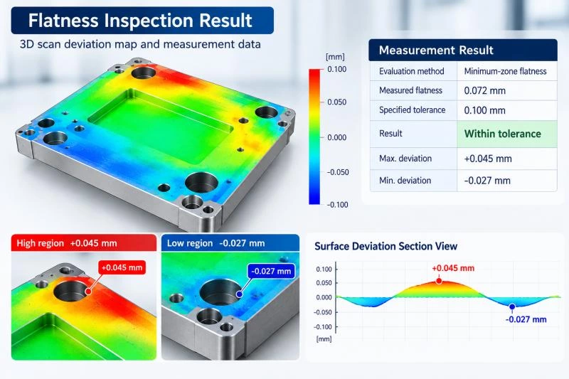
After flatness evaluation is completed, engineers need to determine whether the measured surface meets the specified tolerance and whether the result is reliable enough for a quality decision. Inspection software may display a numerical flatness value, a surface deviation map, and information about the evaluation method.
These outputs serve different purposes. The numerical value supports tolerance assessment, while the deviation map helps identify where surface variation occurs and whether the pattern suggests a manufacturing issue.
Understanding the Measured Flatness Value
Consider a machined mounting surface with a specified flatness tolerance of 0.10 mm. If the inspection software reports a minimum-zone flatness value of 0.072 mm, the measured result falls within the specified tolerance.
| Inspection Parameter | Example Result |
|---|---|
| Specified flatness tolerance | 0.100 mm |
| Measured minimum-zone flatness | 0.072 mm |
| Difference from tolerance limit | 0.028 mm |
| Numerical comparison | Measured value is below the tolerance limit |
Although the numerical result is below the tolerance limit, a final acceptance decision should also consider measurement uncertainty and the applicable decision rule. When the measured value is close to the tolerance boundary, additional verification may be necessary.
Reading a Flatness Deviation Map
A surface deviation map uses colors to visualize the distance between measured points and a selected reference plane. Depending on the software settings, positive and negative deviations may be represented by different colors, while areas close to the reference plane appear in a neutral range.
For example, a deviation map may reveal a raised region near the center of a machined plate or lower regions near its edges. These patterns can help engineers investigate possible deformation, machining variation, or fixture-related effects.
However, color maps must be interpreted carefully. Their appearance depends on the selected reference plane, color scale, filtering settings, and display range. A predominantly green surface does not automatically mean that the part satisfies its flatness tolerance.
When using inspection software such as VisionInspect, engineers should distinguish between visual deviation analysis and the numerical flatness evaluation used for tolerance assessment. The availability of specific evaluation algorithms should be confirmed for the installed software configuration.
What Should a Flatness Inspection Report Include?
A useful inspection report should contain enough information for another engineer to understand how the result was obtained and whether the inspection procedure can be repeated.
- Part identification and inspected surface
- Specified flatness tolerance and applicable drawing requirements
- Measured flatness value and evaluation method
- Scanner and relevant measurement configuration
- Workpiece support and measurement conditions
- Data selection, filtering, and processing settings
- Measurement uncertainty or reference to the applicable decision rule, where required
- Surface deviation visualization and inspection conclusion
Documenting these details is particularly important when comparing measurements across production batches, investigating quality disputes, or evaluating changes in manufacturing processes.
3D Scanning vs Traditional Flatness Measurement Methods
Several measurement methods can be used to evaluate flatness, including optical 3D scanning, coordinate measuring machines (CMMs), and surface plates with suitable contact measurement instruments. Each method has advantages and limitations depending on the component, tolerance, and inspection objective.
Optical 3D scanning is especially useful when broad surface coverage and visualization of geometric variation are important. Contact-based methods may be preferable for certain precision surfaces, restricted measurement areas, or applications requiring a well-established tactile measurement procedure.
| Measurement Method | Typical Strength | Key Limitation |
|---|---|---|
| Optical 3D Scanning | Dense surface data and visual deviation analysis | Sensitive to optical access, surface properties, and measurement setup |
| Contact CMM | Controlled geometric measurement with tactile probing | Surface coverage and measurement time depend on the probing strategy |
| Surface Plate and Indicator | Practical comparative checks for suitable components | Results depend on support conditions, measurement procedure, and interpretation |
For large or geometrically complex parts, optical scanning can help engineers understand the distribution of surface variation rather than examining only a limited number of points. However, greater point density does not automatically provide lower measurement uncertainty.
For very tight tolerances, the measurement method should be selected based on demonstrated capability. In some cases, optical scanning is useful for identifying deformation patterns, while a suitable contact or reference measurement method is used for final verification.
Industrial Applications of 3D Flatness Inspection
Flatness inspection is relevant to many industrial components, particularly where surface geometry affects assembly, sealing, positioning, or subsequent machining. The value of 3D scanning depends on the size of the surface, its accessibility, and the type of variation engineers need to evaluate.
Machined Mounting Surfaces
Mounting surfaces on machine bases, gearbox housings, and structural components must provide appropriate contact with mating parts. Excessive surface variation can contribute to uneven seating, assembly stress, or alignment problems.
3D scanning can help visualize surface deviations across accessible mounting areas, allowing engineers to identify localized high or low regions and investigate machining consistency.
Cast and Forged Components
Castings and forgings may exhibit dimensional variation caused by cooling, residual stress, or manufacturing processes. Before machining or assembly, engineers may need to evaluate the shape of large accessible surfaces and identify areas requiring additional processing.
Optical scanning provides geometric data that can support surface evaluation and machining planning. The measurement procedure should distinguish actual flatness requirements from broader surface profile or machining allowance assessments.
Thin-Walled and Sheet Metal Components
Thin-walled parts can experience distortion during forming, machining, welding, or heat treatment. Their measured geometry may also change depending on how they are supported during inspection.
3D scanning can help identify localized deformation and compare surface conditions across production stages. However, the inspection setup must be carefully controlled to avoid introducing fixture-related distortion.
EV Battery Housings and Structural Interfaces
Battery housings and structural assemblies may contain mounting surfaces and sealing interfaces with defined geometric requirements. Flatness inspection can help assess whether these surfaces provide suitable conditions for downstream assembly.
For large components, scanning can provide broad surface coverage and help engineers investigate deformation patterns. Acceptance decisions should be based on the specific drawing requirements and the measurement capability of the selected system.
Precision Mechanical Components
Precision plates, brackets, housings, and mechanical interfaces may require flatness verification to support assembly and functional performance. For accessible surfaces with suitable tolerances, 3D scanning can provide both numerical measurements and a visual representation of surface variation.
When tolerances approach the measurement capability of the optical system, engineers should consider an alternative or complementary inspection method.
When Should You Use 3D Scanning for Flatness Inspection?
3D scanning is a practical option for flatness inspection when engineers need broad surface coverage, detailed visualization of geometric variation, or repeatable digital measurement records. However, its suitability depends on the component's geometry, surface condition, tolerance, and required measurement uncertainty.
The most appropriate inspection method is not necessarily the one that captures the greatest number of points. It is the method that can evaluate the specified surface reliably under the required measurement conditions.
When 3D Scanning Is a Suitable Choice
- Large or accessible surfaces: Optical scanning can capture extensive surface geometry and help identify localized high and low regions.
- Surface deformation analysis: Dense measurement data supports the investigation of warpage, distortion, and manufacturing variation.
- Repeated production inspection: A controlled scanning procedure can support consistent data collection and digital quality records.
- Complex industrial components: Scanning can provide geometric information across multiple accessible surfaces within a single inspection workflow.
- Visual quality analysis: Surface deviation maps help engineers locate areas that require further investigation.
When Another Measurement Method May Be Preferable
- Extremely tight tolerances: A contact measurement system or specialized metrology instrument may be more appropriate when optical measurement uncertainty is too large relative to the tolerance.
- Limited optical access: Deep recesses, obstructed surfaces, or inaccessible regions may prevent complete surface acquisition.
- Difficult optical surfaces: Transparent or highly reflective materials may require preparation that is unsuitable for the required measurement.
- Small, critical contact areas: A targeted tactile measurement strategy may be more practical when only a limited precision surface requires verification.
- Unverified measurement capability: If the scanner's performance has not been validated for the application, the result should not be used as the sole basis for a critical acceptance decision.
For demanding inspection tasks, combining optical scanning with a suitable reference measurement method may provide a more complete understanding of surface geometry and measurement reliability.
Conclusion
Measuring flatness with a 3D scanner involves capturing surface coordinates, selecting valid measurement data, applying an appropriate plane evaluation method, and comparing the resulting flatness value with the specified tolerance.
Optical 3D scanning is particularly valuable when engineers need to examine surface variation across large or complex components. Its ability to capture dense geometric data can support deviation analysis, manufacturing investigations, and digital inspection reporting.
However, reliable flatness measurement depends on more than scanning resolution. Workpiece support, surface properties, registration quality, data filtering, evaluation algorithms, and measurement uncertainty can all influence the final result.
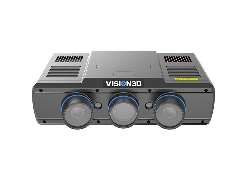
For industrial applications, VISION3D provides PowerScan 3D scanning solutions for capturing component geometry and VisionInspect software for dimensional inspection workflows. The appropriate scanner configuration and supported flatness evaluation functions should be confirmed against the specific measurement requirements.
If you are evaluating 3D scanning for flatness inspection, contact VISION3D to discuss your component dimensions, surface characteristics, flatness tolerance, and inspection objectives.
Frequently Asked Questions
Can a 3D scanner accurately measure flatness?
Yes, an industrial 3D scanner can measure flatness when its measurement performance is suitable for the specified tolerance. Accuracy depends on the scanner, surface condition, measurement setup, data processing, and evaluation method. For tight tolerances, measurement uncertainty should be verified before using the result for acceptance decisions.
How is flatness calculated from a point cloud?
Flatness is evaluated by analyzing the spatial coordinates of measured surface points. Under a minimum-zone evaluation, the software determines the smallest separation between two parallel planes that contain the evaluated points. A least-squares fitted plane can also be used for deviation analysis, but its deviation range is not necessarily the minimum-zone flatness value.
Does flatness measurement require CAD data?
No. Flatness is a form tolerance that evaluates a surface independently of an external datum. A measured point cloud can be evaluated for flatness without a CAD model, provided the inspection software supports the required method. CAD data may still be useful for identifying the inspection area or analyzing other geometric characteristics.
Is a higher-resolution 3D scanner always better for flatness measurement?
Not necessarily. Higher point density may reveal more surface detail, but it does not automatically improve measurement accuracy. Scanner performance, systematic errors, environmental conditions, and data processing can have a greater influence on the reliability of the flatness result.
Can 3D scanning measure flatness on large metal parts?
Yes, provided the scanner can cover the required surface and its measurement capability is appropriate for the specified tolerance. Large components may require multiple scans, careful registration, stable support, and environmental control to avoid introducing artificial geometric variation.
What is the difference between flatness and surface roughness?
Flatness describes the overall form variation of a surface relative to an ideal plane, while surface roughness describes smaller-scale surface texture. They are different measurement characteristics and may require different instruments, sampling strategies, and filtering methods. A 3D scanner suitable for flatness inspection is not necessarily suitable for measuring surface roughness.