Point Cloud vs Mesh: What's the Difference?
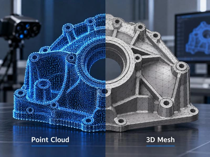
A point cloud and a mesh are two common ways of representing three-dimensional objects, but they store and describe geometry differently. A point cloud consists of individual points positioned in 3D space, while a mesh connects vertices with edges and faces to represent an object's surface.
Both are widely used in 3D scanning, reverse engineering, digital modeling, and industrial inspection. However, choosing between them depends on what you need to do with the data. Point clouds preserve sampled spatial information, while meshes provide a connected surface representation that is often easier to visualize, edit, or prepare for downstream applications.
Understanding the differences between point clouds and meshes helps engineers select the right data format, avoid unnecessary processing, and maintain reliable measurement results.
What Is a Point Cloud?
A point cloud is a collection of data points that represent the shape and position of an object or environment in three-dimensional space. Each point contains spatial coordinates, typically expressed as X, Y, and Z values. Depending on the scanning technology, points may also contain color, intensity, or other measurement information.
Point clouds are commonly generated by 3D laser scanners, structured light scanners, LiDAR systems, and photogrammetry software. These technologies capture spatial information from physical surfaces and convert it into digital datasets.
In industrial 3D scanning, point clouds provide the geometric information needed to analyze manufactured components, inspect dimensions, and compare physical parts with their original designs.
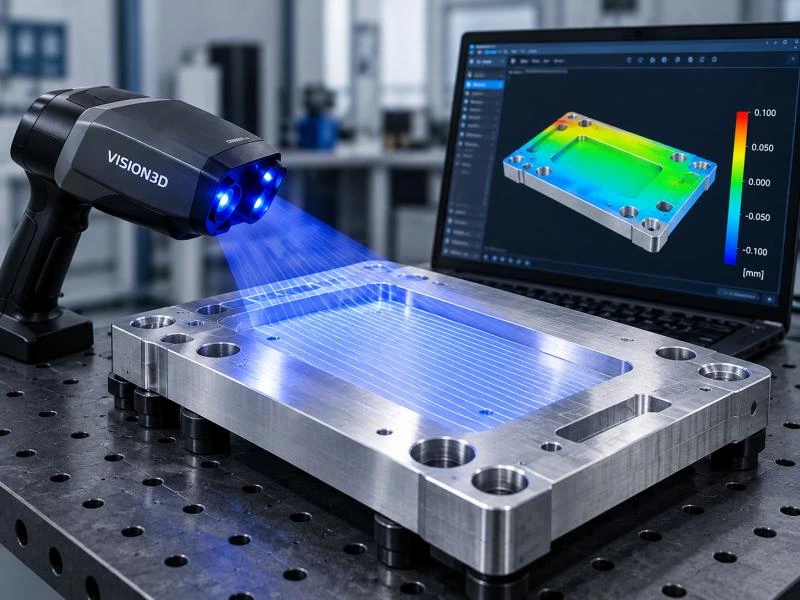
For example, when a precision-machined component is scanned, the resulting point cloud contains thousands or millions of measured positions across its visible surfaces. Engineers can use these points to evaluate geometric features, identify deviations, or prepare the data for further processing.
Unlike a mesh, a point cloud does not inherently define how neighboring points connect. It represents sampled positions rather than an explicitly connected surface.
Key characteristics of point clouds include:
- Discrete spatial data: Each point represents a sampled location in 3D space.
- Flexible data density: Complex regions can contain more points depending on scanning conditions and processing methods.
- No inherent surface connectivity: Points do not automatically form edges or faces.
- Measurement applications: Point clouds can support dimensional inspection, surface analysis, and geometric feature extraction.
Point clouds are particularly useful when engineers need to work with sampled surface measurements before applying additional geometric reconstruction.
What Is a 3D Mesh?
A 3D mesh is a digital representation of an object's surface constructed from interconnected vertices, edges, and faces. Unlike a point cloud, which stores individual spatial points, a mesh defines relationships between those points to form a connected geometric structure.
Most meshes generated from 3D scanning use triangles, although quadrilateral and other polygon types are also common in computer graphics and modeling.
A triangular mesh contains three main elements:
- Vertices: Points defining positions in 3D space.
- Edges: Connections between vertices.
- Faces: Triangular or polygonal surfaces formed by connected vertices.
Together, these elements create a surface representation that can describe the shape of a scanned object.
For example, after scanning a metal casting, specialized software can reconstruct a triangular mesh from the captured point cloud. The resulting mesh provides a continuous-looking surface that can be visualized, analyzed, or exported for further processing.
Meshes are widely used in reverse engineering, 3D printing, computer-aided inspection, and digital visualization. In industrial applications, a mesh can also serve as the measured surface for comparison against a nominal CAD model.
However, a mesh is not the same as a parametric CAD model. While a mesh describes geometry through connected polygons, a CAD model may contain mathematically defined surfaces, dimensions, and editable design features.
The main advantage of a mesh is its explicit surface structure, which makes it useful for applications that require surface visualization, geometric analysis, or manufacturing preparation.
Point Cloud vs Mesh: Key Differences
The main difference between a point cloud and a mesh lies in how they represent 3D geometry. A point cloud stores individual spatial measurements, while a mesh connects vertices to form a surface. This distinction affects how the data is processed, visualized, and used in applications such as dimensional inspection, reverse engineering, and 3D printing.
The following table compares their key characteristics.
| Feature | Point Cloud | 3D Mesh |
|---|---|---|
| Data Structure | Individual points defined by 3D coordinates | Connected vertices, edges, and polygonal faces |
| Surface Representation | Discrete samples without explicit surface connectivity | Polygonal representation of an object's surface |
| Data Source | Typically obtained directly from 3D scanning or spatial measurement | Generated through surface reconstruction, modeling, or other processing methods |
| Geometric Accuracy | Depends on measurement quality, point density, and processing | Depends on source data, reconstruction methods, and mesh resolution |
| File Size | Varies with point count, attributes, and file format | Varies with polygon count, topology, and file format |
| Visualization | Displays sampled points; sparse areas may appear incomplete | Provides connected surfaces that are easier to render as solid-looking objects |
| Editing | Supports filtering, registration, segmentation, and point-level processing | Supports surface editing, smoothing, remeshing, and topology modification |
| Common File Formats | XYZ, PLY, PCD, E57 | STL, OBJ, PLY, 3MF |
| Industrial Applications | Dimensional measurement, feature extraction, and surface analysis | Surface comparison, reverse engineering workflows, and 3D printing preparation |
Neither representation is inherently more accurate or efficient. A dense point cloud may preserve detailed sampled geometry, but it does not automatically provide a continuous surface. A mesh makes surface relationships explicit, although reconstruction and smoothing can introduce geometric changes.
For industrial measurement, the choice depends on the inspection task and the software being used. Some dimensional inspection workflows operate directly on point clouds, while others use meshes for surface-based analysis or comparison with CAD models.
Advantages and Limitations of Point Clouds and Meshes
Point clouds and meshes offer different advantages depending on the application. Understanding their limitations is important when preparing 3D scan data for measurement, modeling, or manufacturing.
Advantages of Point Clouds
Point clouds retain sampled spatial information from the scanning process. Engineers can analyze individual measured positions, identify geometric features, and process the data without first constructing a connected surface.
They are particularly useful for dimensional inspection, registration, and geometric analysis. Point clouds can also represent irregular or incomplete surfaces without requiring the software to fill missing areas.
Limitations of Point Clouds
Because point clouds lack explicit surface connectivity, some operations require additional processing. Sparse measurements, occluded regions, and noisy data can make surface interpretation difficult.
Large point clouds may also require significant memory and processing resources, particularly when handling high-resolution scans of complex industrial components.
Advantages of 3D Meshes
Meshes provide a connected surface representation, making them suitable for visualization, surface-based analysis, and downstream modeling operations.
In industrial applications, a mesh can be used to evaluate surface deviations, prepare scanned geometry for reverse engineering, or create printable models. Its polygonal structure also supports operations such as surface smoothing, mesh repair, and geometric editing.
Limitations of 3D Meshes
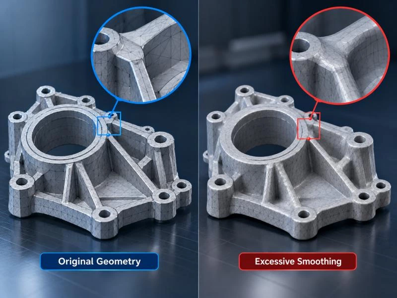
Mesh quality depends heavily on the original scan data and reconstruction process. Excessive smoothing can remove small geometric details, while incorrect surface reconstruction may introduce artificial features.
Missing scan data can also lead to holes or inaccurate reconstructed surfaces. Automatically filling these areas may produce geometry that was not actually measured.
For precision inspection, engineers should therefore verify that mesh processing has not altered critical dimensions or surface features beyond acceptable tolerances.
Ultimately, point clouds are valuable for working with sampled measurement data, while meshes are useful when a connected surface representation is required. The best choice depends on the intended analysis, available software tools, and accuracy requirements.
How to Convert a Point Cloud into a Mesh
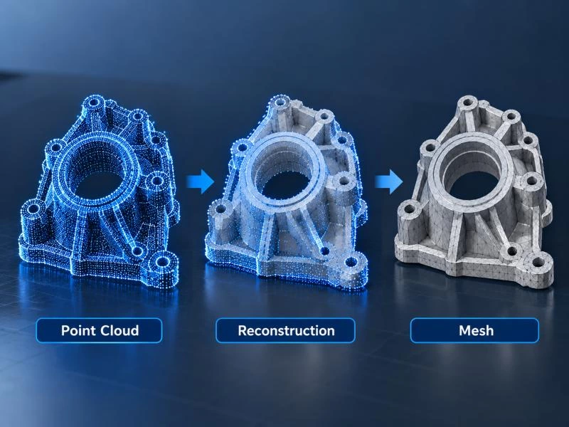
Converting a point cloud into a mesh involves reconstructing a connected surface from individual 3D points. This process, known as point cloud to mesh conversion or surface reconstruction, transforms sampled spatial data into a polygonal model that can be used for visualization, inspection, reverse engineering, and 3D printing.
The conversion process varies depending on the scanning technology, software, and intended application. However, most workflows follow several common stages.
Step 1: Prepare the Point Cloud
Before surface reconstruction, the point cloud is checked for duplicate points, obvious outliers, and incomplete scan regions. If multiple scans were captured, they must be registered into a common coordinate system.
The goal is to establish a consistent dataset for reconstruction. Excessive filtering should be avoided when small geometric features are important for dimensional inspection.
Step 2: Estimate Surface Orientation
Many reconstruction algorithms use surface normals to estimate the local orientation of the scanned geometry. A normal is a vector that describes the approximate direction perpendicular to a surface.
Consistent normal orientation helps reconstruction software determine how neighboring points should form a surface. Incorrect normals may produce distorted or incorrectly connected regions.
Step 3: Reconstruct the Mesh Surface
Specialized software connects or interpolates the point data to generate polygonal faces, usually triangles. Common reconstruction approaches include triangulation-based methods and implicit surface reconstruction.
The selected method affects how well the resulting mesh represents sharp edges, curved surfaces, narrow gaps, and other geometric features. Reconstruction settings should therefore match the characteristics of the scanned object.
Step 4: Inspect and Refine the Mesh
After reconstruction, the mesh is examined for holes, overlapping faces, non-manifold geometry, and unwanted surface irregularities.
Depending on the application, the mesh may require local repair, smoothing, or polygon reduction. However, these operations should be applied carefully because they can modify the reconstructed geometry.
For industrial inspection, areas containing critical dimensions should not be automatically smoothed or filled without verification against the original measurement data.
Step 5: Export and Validate the Mesh
The completed mesh can be exported in formats such as STL, OBJ, or PLY, depending on the software and downstream application.
Before using the model for precision measurement, engineers should verify its coordinate system, units, geometric completeness, and deviation from the original point cloud.
A visually smooth mesh is not necessarily a geometrically accurate one. Validation helps ensure that the reconstruction process has preserved the features needed for the intended application.
Does Converting Point Clouds to Meshes Affect Accuracy?
Converting a point cloud into a mesh can affect geometric accuracy, but it does not necessarily reduce it. The outcome depends on the quality of the original measurements, the reconstruction algorithm, and the processing settings.
A point cloud contains sampled positions from a physical surface. During mesh reconstruction, software estimates the surface between these positions. Since the surface is inferred rather than directly measured at every location, differences can occur between the reconstructed mesh and the original geometry.
Surface Reconstruction Errors
Reconstruction algorithms may introduce deviations when point density is insufficient or the scanned surface contains sharp edges, narrow grooves, or complex transitions.
For example, a mesh generated from sparse points around a small radius may not accurately reproduce the original curvature. Increasing the polygon count alone cannot recover geometric details that were never captured.
Smoothing and Detail Loss
Mesh smoothing can reduce visible noise and improve surface appearance, but excessive smoothing may alter edges, corners, holes, and other important features.
For manufactured components with tight tolerances, these changes can affect dimensional inspection results. Smoothing settings should therefore be selected according to the required measurement accuracy rather than visual appearance alone.
Hole Filling and Missing Geometry
When a scanner cannot capture certain areas because of occlusion or limited access, the resulting point cloud may contain gaps.
Mesh software can fill these gaps by estimating the missing surface. Although useful for visualization or 3D printing, the generated geometry should not be treated as directly measured data.
For quality inspection, dimensions derived from reconstructed but unmeasured regions may be unreliable.
Mesh Resolution and Geometric Detail
Mesh resolution influences how closely polygonal surfaces can approximate curved or complex geometry. A coarse mesh may simplify small features, while a finer mesh can represent more detail when sufficient source data is available.
However, higher polygon density does not automatically improve measurement accuracy. The mesh remains limited by the original scan quality and reconstruction method.
How to Preserve Accuracy During Conversion
For industrial 3D inspection, engineers should compare the reconstructed mesh with the original point cloud, review critical geometric features, and evaluate whether processing deviations are acceptable for the measurement task.
When strict dimensional tolerances are involved, the inspection workflow should also account for scanner uncertainty, registration errors, and the influence of data processing.
The key principle is that mesh quality and measurement accuracy are not the same thing. A well-constructed mesh can represent scanned geometry effectively, but its suitability for precision inspection must be verified rather than assumed.
Point Cloud vs Mesh for Industrial 3D Inspection
In industrial 3D inspection, both point clouds and meshes can be used to evaluate manufactured parts, identify geometric deviations, and verify dimensional requirements. The choice depends on the features being measured, the inspection software, and the accuracy required for the application.
Industrial 3D scanners, including structured light and laser scanning systems, capture surface geometry that can be processed as point clouds or reconstructed into meshes. These datasets support different stages of dimensional inspection and quality control.
Using Point Clouds for Dimensional Measurement
Point clouds are useful when inspection software needs to analyze sampled surface positions directly. Engineers can extract geometric features, fit reference planes or cylinders, and calculate dimensions based on measured coordinates.
For example, when inspecting a machined metal component, point cloud data can be used to evaluate the position of accessible holes, measure distances between geometric features, or assess the flatness of a surface.
Because the measurements are derived from sampled positions, the results depend on point distribution, scanning conditions, and the algorithms used for feature fitting. Some inspection tasks may require additional measurements or alternative equipment, particularly when critical features are difficult to capture optically.
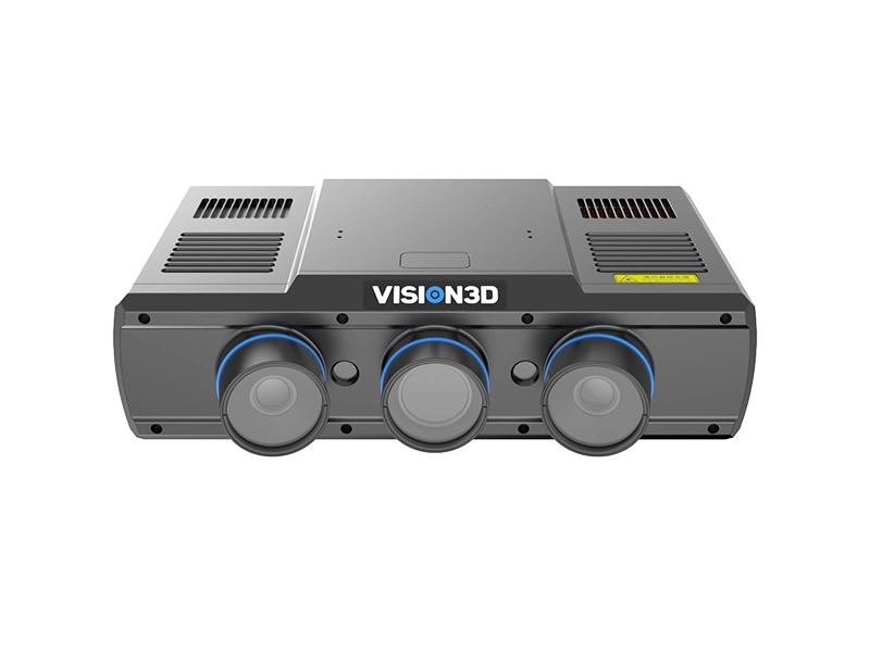
Industrial scanning systems such as the PowerScan Series can support the acquisition of detailed surface data for dimensional inspection and geometric analysis.
Using Meshes for Surface Inspection
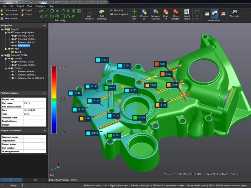
Meshes are often useful when inspection tasks involve evaluating continuous surface geometry. A reconstructed mesh provides a connected representation that can be compared with a nominal CAD model to identify differences in shape.
For instance, engineers inspecting a cast or formed component may use a mesh to visualize surface deviations across complex curved regions. Color deviation maps can help identify areas where the manufactured part differs from its intended geometry.
However, a mesh does not automatically provide more reliable measurements than a point cloud. Its accuracy depends on the original scanning data and the reconstruction process, particularly around sharp edges, small holes, and incomplete surfaces.
Choosing the Right Data for Quality Control
For dimensional inspection, the most appropriate representation depends on the measurement objective rather than a fixed preference for point clouds or meshes.
Point clouds may be suitable for direct geometric feature fitting, while meshes can be convenient for surface-based comparison and visualization. Many industrial inspection workflows support both representations, allowing engineers to use different processing methods for different features.
For automated production environments, the AutoScan Series provides 3D scanning solutions that can be incorporated into automated inspection workflows. The resulting scan data can then be evaluated using compatible inspection software according to the required measurement tasks.
Regardless of the representation selected, reliable inspection requires appropriate data acquisition, alignment, processing, and validation. Engineers should also distinguish between directly measured surfaces and geometry estimated during reconstruction.
Point Cloud vs Mesh vs CAD Model
Point clouds, meshes, and CAD models all represent three-dimensional geometry, but they are created differently and serve different purposes. Understanding these distinctions is particularly important in industrial inspection and reverse engineering.
A point cloud represents sampled positions on an object's surface. It is commonly generated through 3D scanning and provides spatial information about the physical component.
A mesh represents geometry using connected vertices and polygonal faces. It is often reconstructed from point cloud data and is suitable for surface visualization, geometric analysis, and certain manufacturing workflows.
A CAD model typically describes an engineered design using mathematically defined geometry, such as planes, cylinders, curves, and parametric surfaces. Depending on the modeling system, it may also contain dimensions, constraints, and editable design features.
| Feature | Point Cloud | Mesh | CAD Model |
|---|---|---|---|
| Geometry Representation | Discrete 3D points | Connected polygonal surfaces | Mathematical curves, surfaces, and solids |
| Typical Source | 3D scanning or spatial measurement | Surface reconstruction or 3D modeling | Engineering design or reverse engineering |
| Surface Connectivity | Not inherently defined | Explicit polygon connectivity | Defined by the CAD geometry and topology |
| Design Editability | Limited to point-level operations | Supports mesh editing | May support parametric feature editing |
| Common Formats | XYZ, PCD, E57 | STL, OBJ, PLY | STEP, IGES, native CAD formats |
| Typical Industrial Use | Measured geometry and feature analysis | Surface inspection and reconstruction | Product design and nominal geometry reference |
In a typical industrial workflow, a physical component is scanned to obtain geometric data. That data may be processed as a point cloud or converted into a mesh. If an editable engineering model is required, additional reverse engineering operations may be performed to reconstruct CAD geometry.
Importantly, converting a point cloud into a mesh does not automatically create a parametric CAD model. Mesh-to-CAD reconstruction is a separate process that may involve feature recognition, surface fitting, and engineering interpretation.
For quality inspection, the original CAD model often serves as the nominal reference, while the point cloud or mesh represents the measured component. Comparing the two allows engineers to evaluate geometric deviations and determine whether the manufactured part meets specified requirements.
Which Should You Use: Point Cloud or Mesh?
Choosing between a point cloud and a mesh depends on how the 3D data will be used. Both can represent scanned objects, but their suitability varies according to the measurement task, processing requirements, and intended output.
For industrial applications, the decision should be based on the following considerations.
| Application | Recommended Representation | Reason |
|---|---|---|
| Direct Analysis of Scanned Points | Point Cloud | Preserves sampled coordinates for geometric analysis and feature fitting. |
| Complex Surface Visualization | Mesh | Provides connected surfaces for displaying object geometry. |
| Dimensional Inspection | Point Cloud or Mesh | Depends on the measurement features and inspection software. |
| CAD Deviation Analysis | Point Cloud or Mesh | Both can support comparison with nominal CAD geometry. |
| Reverse Engineering | Both | Point clouds provide measured data, while meshes can support surface reconstruction and CAD modeling. |
| 3D Printing | Mesh | Manufacturing workflows commonly require a suitable printable surface or solid representation. |
If the goal is to analyze measured coordinates or extract geometric features directly, a point cloud may be the preferred starting point. If the application requires a connected surface for visualization, mesh editing, or 3D printing, a mesh is generally more suitable.
For precision manufacturing, it is often useful to retain the original point cloud alongside any reconstructed mesh. This allows engineers to verify processed geometry and return to the measured data when necessary.
Ultimately, the best representation is the one that supports the required workflow without introducing unnecessary processing or compromising important geometric information.
Frequently Asked Questions
Is a point cloud the same as a mesh?
No. A point cloud consists of individual 3D points without inherent surface connectivity. A mesh connects vertices through edges and faces to represent an object's surface. Both describe three-dimensional geometry, but they use different data structures.
Can you convert a point cloud into a mesh?
Yes. Point clouds can be converted into meshes using surface reconstruction algorithms. The process typically involves preparing the point data, estimating surface relationships, generating polygonal faces, and checking the reconstructed geometry.
Is a mesh more accurate than a point cloud?
Not necessarily. A mesh is not inherently more accurate than a point cloud. Measurement accuracy depends on the original scan data, reconstruction algorithms, and processing settings. Mesh generation may introduce deviations, particularly around small features or incomplete surfaces.
Can point clouds be used for 3D printing?
Point clouds are generally not used directly in conventional 3D printing workflows. They are typically converted into suitable mesh or solid models before printing. The resulting geometry may require additional repair to meet manufacturing requirements.
What is the difference between a mesh and a CAD model?
A mesh represents an object's surface using connected polygons, while a CAD model typically uses mathematically defined curves, surfaces, and solids. CAD models may also contain editable dimensions and design features, making them more suitable for engineering design and modification.
Conclusion
The difference between a point cloud and a mesh comes down to how each represents 3D geometry. Point clouds store sampled spatial measurements, while meshes organize vertices into connected surfaces. Neither is universally better; the appropriate choice depends on the application, software capabilities, and required geometric accuracy.
In industrial 3D inspection, both representations play important roles in dimensional measurement, surface analysis, and comparison with CAD models. Understanding their differences helps engineers select efficient processing workflows and maintain reliable inspection results.
VISION3D offers industrial 3D scanning and automated inspection solutions for capturing and analyzing complex component geometry. Explore our PowerScan Series and VScan M Series to learn more about 3D measurement technologies for manufacturing and quality control.