First Article Inspection with 3D Scanning: A Faster Production Validation Workflow
Before a new component enters full-scale production, manufacturers need to verify that the actual part can be produced according to the original design requirements. First Article Inspection (FAI) provides a structured validation process to confirm that a manufactured component meets engineering drawings, CAD models, dimensional specifications, and quality requirements.
For modern industrial parts, however, first article inspection can become challenging. Complex geometries, increasing feature requirements, and strict dimensional tolerances require manufacturers to collect more measurement information before production approval.
Traditional inspection methods may require engineers to measure individual features one by one, which can increase inspection time and delay the transition from prototype development to mass production.
3D scanning provides a more efficient approach by capturing complete surface geometry and enabling direct comparison between the manufactured part and its digital design. With full-field measurement, CAD comparison, and digital inspection reporting, 3D scanning helps manufacturers identify deviations earlier and improve production validation efficiency.
What Is First Article Inspection?
First Article Inspection (FAI) is a quality verification process used to confirm that the first manufactured part meets the defined product requirements before regular production begins.
The purpose of FAI is not only to check whether a single component passes inspection. It also validates whether the current manufacturing process, tooling, and production conditions can consistently produce parts that match the intended design.
A typical first article inspection verifies:
- CAD model requirements
- Engineering drawing specifications
- Critical dimensions
- Geometric characteristics
- Assembly interfaces
- Product specifications
By completing FAI before mass production, manufacturers can identify potential issues related to machining, forming, casting, tooling, or assembly processes before these problems affect larger production volumes.
When Is First Article Inspection Required?
FAI is commonly required when changes may affect product quality or manufacturing consistency.
| Situation | Purpose of First Article Inspection |
|---|---|
| New product introduction | Verify that the manufacturing process can produce the designed component |
| Design changes | Confirm updated geometry and requirements are correctly implemented |
| Tooling or process changes | Validate production changes do not affect part quality |
| Production transfer | Ensure consistency after moving production to another location |
Industries such as aerospace, automotive, and precision manufacturing rely on FAI to provide documented evidence that a component is ready for production.
Why Traditional First Article Inspection Can Become a Bottleneck
First Article Inspection plays an important role in production validation, but traditional inspection workflows can become time-consuming when dealing with complex industrial components. Modern parts often include numerous features, tight tolerances, and complicated surface geometries that require comprehensive verification before production approval.
For simple components, checking several critical dimensions may be sufficient. However, for advanced manufactured parts, engineers need more complete measurement information to understand whether the entire component meets the original design requirements.
Complex Parts Require More Inspection Information
Many industrial components contain a large number of characteristics that must be verified during FAI, including:
- Mounting holes and connection points
- Surface profiles
- Flatness requirements
- Assembly interfaces
- Complex curved surfaces
- Geometric tolerances
Traditional measurement methods often focus on predefined inspection points. While this approach is effective for specific characteristics, it may provide limited information about the overall condition of a complex part.
Feature-by-Feature Measurement Requires More Time
A conventional inspection workflow usually follows a feature-based process:
Select Feature → Measure → Record Result → Compare Requirement → Move to Next Feature
For components with many inspection requirements, this process can require significant programming, setup, and measurement time.
When a first article does not meet requirements, additional measurements may also be needed to understand the source of the deviation, which can further extend the validation cycle.
Production Approval Requires Faster Feedback
During new product introduction, manufacturers often need to quickly identify problems and adjust production processes before moving into full-scale manufacturing.
Delays in first article inspection can affect:
- Production schedules
- Tooling adjustments
- Engineering verification
- Product launch timelines
For this reason, manufacturers increasingly look for inspection methods that can provide comprehensive measurement data while reducing the time required for production validation.
How 3D Scanning Improves First Article Inspection
3D scanning improves first article inspection by capturing complete surface geometry and creating a digital representation of the manufactured component. Instead of measuring only selected features, manufacturers can analyze the relationship between the actual part and the original CAD design.
This allows engineering teams to identify dimensional variations faster and make more informed decisions before production begins.
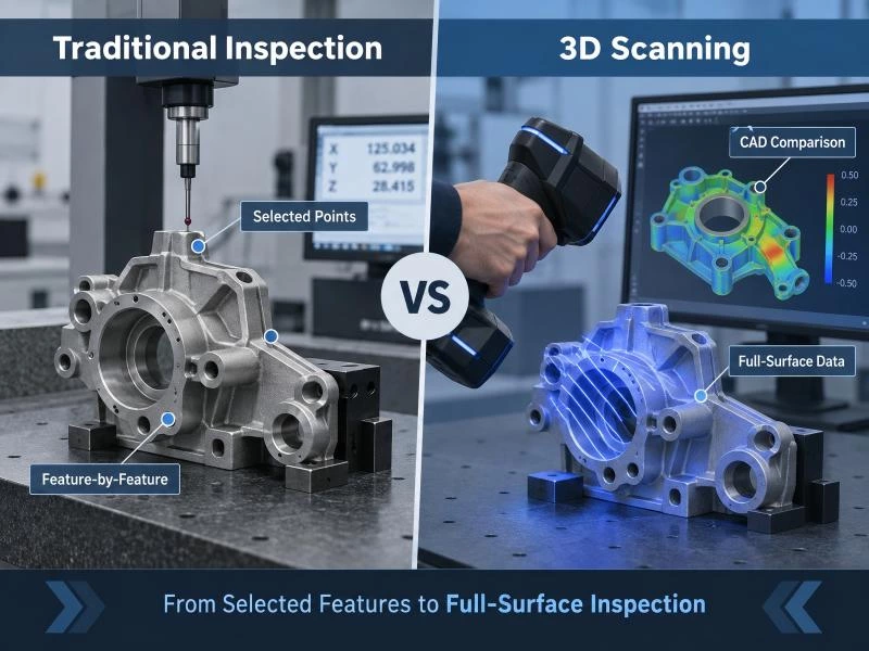
From Individual Measurements to Full-Surface Inspection
Traditional inspection methods typically focus on specific measurement locations. In contrast, 3D scanning captures dense surface information across the complete visible geometry of the part.
| Traditional Inspection | 3D Scanning Inspection |
|---|---|
| Measures selected features | Captures complete surface geometry |
| Requires predefined measurement locations | Provides broader geometric evaluation |
| Limited visualization of overall deviation | Supports color deviation maps and CAD comparison |
| Additional measurements may be needed for investigation | Creates reusable digital inspection data |
Faster Detection of Manufacturing Deviations
Because 3D scanning captures the complete part geometry, engineers can quickly identify differences between the manufactured component and the intended design.
Typical inspection results may include:
- CAD deviation comparison
- Surface profile analysis
- Dimensional verification
- Geometric variation analysis
This information helps manufacturers understand whether a problem is related to a specific feature or represents a larger manufacturing variation.
Supporting More Efficient Production Validation
For first article inspection, speed is important because any delay can affect production schedules. By combining 3D data capture, digital comparison, and inspection analysis, 3D scanning helps shorten the time between part manufacturing and engineering evaluation.
A typical scan-based FAI process can include:
- Capture the first article geometry
- Align scan data with CAD requirements
- Analyze dimensional deviations
- Verify critical characteristics
- Create inspection documentation
This digital workflow helps manufacturers move from inspection results to production decisions more efficiently.
A 3D Scanning Workflow for First Article Inspection
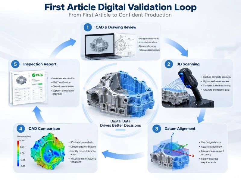
A scan-based FAI workflow should connect the manufactured part directly to its engineering requirements. The goal is not simply to create a 3D model, but to verify whether the first article matches the intended design and is ready for production approval.
A practical workflow can be summarized as:
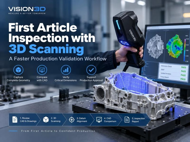
CAD & Drawing Review → 3D Scanning → Datum Alignment → CAD Comparison → Inspection Report
Step 1: Review CAD, Drawings and Inspection Requirements
Before scanning begins, engineers should define the inspection requirements based on the CAD model, engineering drawing, and quality specifications.
Important information may include:
- Nominal geometry
- Critical dimensions
- Datum references
- Tolerance requirements
- Assembly interfaces
- Key product characteristics
This step ensures that the inspection process is based on design intent rather than simply on the geometry that is easiest to measure.
Step 2: Capture the First Article with 3D Scanning
The first manufactured part is then captured using an industrial 3D scanner. The objective is to obtain sufficient surface coverage for dimensional evaluation while ensuring that datum areas and critical features are included in the dataset.
Depending on the application, 3D scanning can support first article inspection of:
- CNC machined components
- Sheet metal parts
- Castings
- Molded components
- Large structural parts
For complex parts, full-surface data provides more inspection information than a small number of discrete measurement points and allows additional characteristics to be evaluated after scanning.
Step 3: Align Scan Data with the Design Reference
After scanning, the measured data must be aligned with the CAD model before inspection results can be evaluated. The alignment method is important because it determines how deviations are interpreted.
For formal first article inspection, the scan data should follow the datum structure defined in the engineering drawing whenever applicable.
A typical reference relationship may use:
Primary Datum → Secondary Datum → Tertiary Datum
This helps ensure that measured deviations reflect the intended functional relationship between the manufactured component and the design.
Why Best-Fit Alignment Should Be Used Carefully
Best-fit alignment can be useful for visualizing overall shape differences, but it is not always appropriate for formal FAI evaluation. Because the software minimizes deviation across the complete surface, best-fit alignment may change how local errors appear.
When dimensions or geometric tolerances are defined relative to specific datums, the alignment method should follow those design references rather than relying only on a global best fit.
Step 4: Compare the First Article with CAD
Once the scan data is correctly aligned, the measured component can be compared with the nominal CAD model.
Typical analysis may include:
- 3D deviation color maps
- Surface profile comparison
- Dimensional measurements
- Feature position verification
- Critical geometric characteristics
A color deviation map gives engineers a quick visual overview of where the first article differs from the design. This can help distinguish isolated feature errors from broader geometric variation across the component.
Critical dimensions and GD&T requirements can then be evaluated according to the drawing and inspection plan. Features that require extremely tight tolerances or cannot be accessed optically may still be verified with another suitable measurement method.
Step 5: Generate the First Article Inspection Report
The final stage is to convert the measurement results into a documented FAI report that supports production approval and traceability.
A digital inspection report may include:
- Nominal and measured values
- Tolerance limits
- Deviation results
- Pass or fail status
- Critical feature verification
- 3D deviation maps
The complete digital workflow becomes:
First Article → 3D Measurement → Design Comparison → Verification → FAI Report → Production Approval
By keeping the inspection process connected to the original design data, manufacturers can reduce manual interpretation and make production decisions more quickly.
3D Scanning vs CMM for First Article Inspection
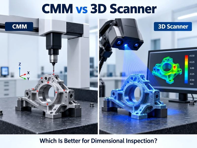
3D scanning and Coordinate Measuring Machines (CMMs) can both be used for first article inspection, but they are suited to different measurement tasks. The best choice depends on part geometry, tolerance requirements, feature accessibility, and the amount of measurement data required.
| FAI Requirement | 3D Scanning | CMM |
|---|---|---|
| Full-surface measurement | Well suited to capturing complete visible geometry | Primarily measures programmed points and features |
| Complex freeform surfaces | Efficient for dense surface comparison | May require additional programming and measurement time |
| Deviation visualization | Supports CAD comparison and 3D color maps | Typically focuses on numerical feature results |
| Very tight critical tolerances | Depends on scanner capability and application | Often well suited to high-precision feature measurement |
| Deep or internal features | Limited by optical accessibility | Probing may provide better access |
For many FAI projects, the two technologies can be complementary rather than direct replacements. 3D scanning can provide fast full-field inspection and reveal overall geometric deviation, while a CMM or another measurement tool can verify selected critical features when required.
The objective is to use the most suitable measurement method for each inspection characteristic while keeping the overall first article validation process efficient.
Applications of 3D Scanning in First Article Inspection
Scan-based FAI is particularly valuable for parts with complex geometry, large surface areas, numerous inspection characteristics, or frequent design and tooling changes. These requirements are common across aerospace, automotive, and precision manufacturing.
Aerospace Manufacturing
Aerospace components often require detailed dimensional verification before production approval. 3D scanning can support inspection of machined components, structural parts, composite surfaces, and tooling by providing full-surface data for comparison with design requirements.
Automotive Manufacturing
Automotive manufacturers frequently validate sheet metal parts, castings, body structures, EV components, and tooling before mass production. Full-field 3D measurement can help identify geometric variation and provide faster feedback during product and process development.
Precision Manufacturing
First article inspection with 3D scanning can also support CNC machining, die casting, injection molding, sheet metal fabrication, and tooling production.
- CNC parts — dimensional and feature verification
- Castings — surface and overall geometry inspection
- Sheet metal — forming accuracy and deformation evaluation
- Molded parts — shape and dimensional consistency
- Tooling — verification before production use
Across these applications, the main advantage is the ability to capture a complete digital record of the first manufactured part and use that data to support faster production decisions.
VISION3D Solutions for First Article Inspection
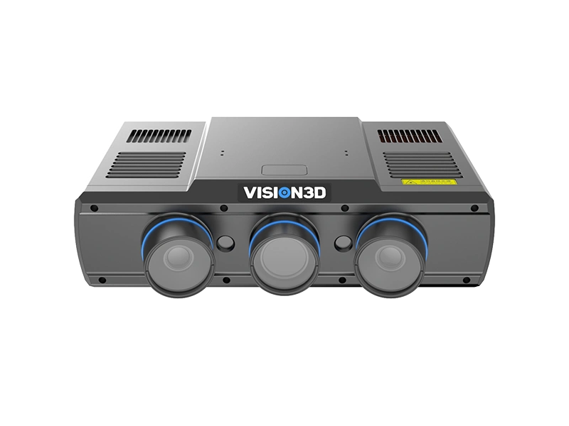
Efficient first article inspection requires not only accurate measurement but also a complete digital workflow from data acquisition to production validation. VISION3D provides industrial 3D scanning solutions that help manufacturers capture, analyze, and verify complex components during new product introduction and manufacturing development.
By combining 3D scanning, CAD comparison, and inspection analysis, manufacturers can create a more efficient FAI process:
Scan → Analyze → Verify → Production Validation
Industrial 3D Scanning for Complete Part Verification
VISION3D 3D scanning solutions are designed for manufacturers that need flexible inspection of complex industrial components. Compared with traditional feature-by-feature measurement, 3D scanning provides complete surface information that supports faster evaluation of part geometry and manufacturing quality.
Typical FAI applications include:
- Prototype validation
- New product introduction
- Tooling verification
- Manufacturing process validation
- Supplier quality inspection
3D Scanning Solutions for Different FAI Requirements
| Solution | FAI Application |
|---|---|
| PowerScan Series | High-accuracy inspection for precision industrial components and dimensional verification |
| VScan M Series | Flexible handheld measurement for complex parts and multi-position inspection |
| AutoScan Series | Automated inspection workflows for repeatable production validation |
From First Article Inspection to Production Validation
The value of first article inspection is not limited to approving a single component. The measurement data generated during FAI can also support future production monitoring, process improvement, and quality traceability.
With a digital inspection workflow, manufacturers can connect the first validated part with future production requirements:
First Article → Digital Measurement → Process Verification → Continuous Improvement
This approach helps manufacturers make faster decisions during product development while building a more reliable quality control process.
FAQ About First Article Inspection with 3D Scanning
What is first article inspection?
First Article Inspection (FAI) is a quality verification process used to confirm that the first manufactured part meets engineering requirements before full production begins.
Can 3D scanning be used for first article inspection?
Yes. 3D scanning can support FAI by capturing complete surface geometry, comparing scan data with CAD models, analyzing deviations, and generating digital inspection results.
How does 3D scanning improve first article inspection?
3D scanning improves FAI efficiency by providing full-surface measurement data instead of only selected measurement points. This helps engineers identify geometric variations and make faster production decisions.
Can 3D scanning replace CMM in first article inspection?
3D scanning and CMM are suitable for different inspection requirements. 3D scanning is effective for complex surfaces and full-field analysis, while CMM remains valuable for certain high-precision feature measurements.
How is 3D scan data compared with CAD during FAI?
The scanned data is aligned with the CAD model according to the required reference system. Engineers can then evaluate dimensional differences, surface deviation, and critical characteristics before production approval.
Conclusion
First Article Inspection is a critical step in ensuring that a new product can move from development into stable production. As industrial components become more complex, manufacturers need inspection methods that provide both accurate measurement and efficient production feedback.
3D scanning improves the FAI process by capturing complete surface geometry, supporting CAD comparison, and providing clear visualization of dimensional variation. This allows engineering and quality teams to identify issues earlier and make better decisions before mass production begins.
For aerospace, automotive, and precision manufacturing applications, combining 3D scanning with digital inspection workflows provides a practical approach to faster production validation and improved manufacturing confidence.
First Article Inspection → Digital Measurement → Production Validation