3D Scanning for Reflective and Black Surfaces: Challenges and Solutions
Why Are Reflective and Black Surfaces Difficult to 3D Scan?
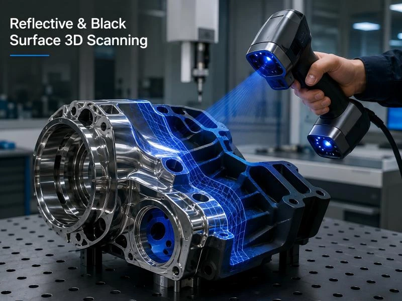
Reflective and black surfaces are among the most challenging materials for optical 3D scanning because they interact with projected light in very different ways. Highly reflective surfaces can return too much light toward the scanner, while black and dark materials may absorb a large portion of the projected light. Both conditions can make it harder for the scanner to capture stable and complete 3D data.
Reflective Surfaces Can Produce Excessive or Unstable Reflections
Polished metals, chrome-plated components, glossy painted surfaces, and machined aluminum often create strong specular reflections. Instead of scattering light evenly back toward the scanner, these surfaces may reflect light in a concentrated direction.
When too much reflected light reaches the sensor, some areas may become overexposed or saturated. Other areas may reflect light away from the sensor completely. The result can include missing scan data, noisy points, unstable surface reconstruction, and reduced measurement reliability.
These challenges are especially common when scanning polished molds, automotive body panels, stainless steel parts, and other components with smooth or glossy finishes.
Black and Dark Surfaces Absorb More Projected Light
Black plastics, rubber, dark coatings, graphite, and some carbon fiber components present the opposite problem. Instead of reflecting too much light, they absorb more of the projected light, leaving the scanner with a weaker return signal.
A weak optical signal can make it difficult to capture fine details, edges, holes, and small geometric features. In some cases, the scanner may require longer exposure settings or stronger light output to obtain sufficient surface data.
The challenge becomes more complicated when a single part contains both dark and bright areas because one fixed exposure setting may not work equally well across the entire surface.
Mixed Surfaces and Complex Geometry Increase Scanning Difficulty
Industrial components rarely have a uniform surface. A single workpiece may combine black plastic, polished metal, painted sections, machined areas, and different levels of reflectivity. This creates large variations in the amount of light returned to the scanner.
Complex geometries can further increase the difficulty. Deep holes, narrow grooves, sharp edges, recessed areas, and curved reflective surfaces may prevent the projected light from reaching the sensor at an ideal angle.
For this reason, successful 3D scanning of reflective and black surfaces depends not only on scanner accuracy, but also on exposure control, light source adjustment, scanning angle, surface condition, and the geometry of the part being measured.
What Happens When Surface Reflectivity Is Not Properly Controlled?
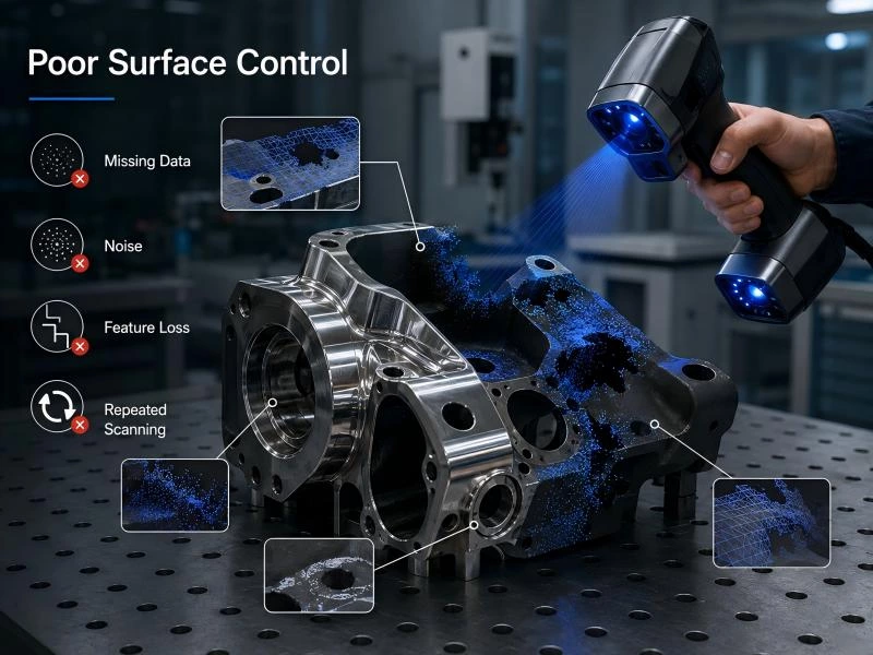
When reflective or dark surfaces are not captured under suitable scanning conditions, the problem is not limited to a few missing points. Poor optical response can affect point cloud completeness, surface reconstruction, feature recognition, and the efficiency of the entire inspection process.
Missing or Incomplete Point Cloud Data
Highly reflective areas may send projected light away from the scanner or overload the sensor, while black surfaces may return too little light. In both cases, parts of the surface can be missing from the point cloud.
Incomplete data becomes especially problematic around curved surfaces, deep recesses, holes, and transitions between materials with different reflectivity. If important inspection areas are not fully captured, additional scans may be required before analysis can continue.
Noise and Unstable Surface Reconstruction
Unstable optical signals can also create noisy points or outliers around reflective regions. Instead of forming a clean and consistent surface, the scanned data may contain irregular points that require additional filtering or processing.
For dimensional inspection, excessive noise can make it more difficult to evaluate surface deviations accurately, particularly when scanned data is aligned with a CAD model for comparison.
Loss of Edges and Fine Geometric Features
Small holes, narrow grooves, sharp edges, and fine contours often require a stable signal to be reconstructed accurately. Reflective highlights or insufficient light from dark surfaces can reduce the clarity of these features.
This is particularly important for precision components where the inspection target may include hole positions, edge profiles, local dimensions, or other small geometric details rather than only the overall shape of the part.
Repeated Scanning Reduces Inspection Efficiency
Surface-related scanning problems can also increase inspection time. Operators may need to adjust exposure settings, change the scanning angle, rescan incomplete areas, or prepare the surface before sufficient data can be obtained.
In a manufacturing environment, this additional work can slow down dimensional inspection and reduce workflow efficiency. For applications involving multiple parts or frequent measurements, improving data acquisition at the scanning stage is therefore just as important as achieving high measurement accuracy.
How to Scan Reflective Surfaces More Accurately
Improving the 3D scanning results of reflective parts usually requires controlling how projected light interacts with the surface. Exposure, scanning angle, ambient lighting, and surface preparation can all affect data quality. The appropriate method depends on the material, surface finish, part geometry, and required measurement accuracy.
Adjust Exposure to Reduce Overexposure
Exposure settings are one of the first parameters to consider when scanning polished metal, glossy coatings, or other highly reflective surfaces. If the sensor receives too much reflected light, local areas may become saturated and produce incomplete or unstable data.
Reducing exposure can help preserve surface information in bright regions. For parts containing both reflective and less reflective areas, multiple or adaptive exposure settings can provide more consistent data across surfaces with different reflectivity.
Optimize the Scanning Angle
Changing the angle between the scanner and the workpiece can reduce direct specular reflections entering the sensor. This is particularly useful for flat polished surfaces, curved metal parts, and glossy automotive panels.
For components with complex geometry, however, one scanning angle may not capture every feature. Operators may need to reposition the scanner or workpiece to obtain sufficient data from edges, recessed areas, and curved surfaces while avoiding strong reflections.
Control Ambient Lighting During Measurement
Strong sunlight, intense factory lighting, and nearby reflective objects can interfere with the projected scanning light and make optical data acquisition less stable. Controlling the measurement environment can therefore improve consistency, especially when inspecting large components on the production floor or performing measurements on site.
Where possible, avoid direct sunlight and strong light sources aimed at the measurement area. A more stable lighting environment allows the scanner to distinguish its projected light from surrounding illumination more reliably.
Use Scanning Spray When Surface Preparation Is Necessary
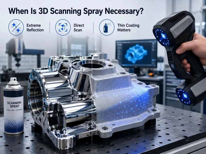
For mirror-like, highly polished, transparent, or extremely reflective surfaces, adjusting exposure and scanning angle may not always be sufficient. A temporary scanning spray can create a more uniform matte surface, reducing specular reflection and making optical data acquisition easier.
Surface treatment should not automatically be applied to every reflective component. Preparing and cleaning the part adds time to the inspection process, while the thickness and uniformity of the applied coating should also be considered in high-accuracy dimensional measurement.
Modern industrial 3D scanners with intelligent exposure and improved optical adaptability can reduce the need for spraying in many applications. For extremely challenging surfaces, however, surface preparation can still be a practical way to obtain more stable and complete 3D data.
When Is Still Necessary?
Modern industrial 3D scanners can handle many reflective and dark surfaces without additional preparation, but scanning spray still has an important role in certain applications. The key is to use it only when optical conditions prevent the scanner from collecting sufficiently stable and complete data.
When Scanning Spray May Be Helpful
Scanning spray is most useful for surfaces that create extreme optical interference, such as mirror-like metal, highly polished components, transparent materials, or parts with very strong localized reflections. By creating a temporary matte coating, the spray reduces specular reflection and helps the scanner receive a more uniform return signal.
Typical examples include polished molds, chrome-plated parts, glass-like materials, and precision metal components with highly reflective finishes.
When Direct Scanning May Be Preferred
Surface preparation is not always practical. Large automotive panels, finished production parts, sensitive components, and high-throughput inspection tasks may be difficult or time-consuming to coat and clean before every scan.
In these situations, direct scanning with suitable exposure control, light source adjustment, and optimized scanning angles can improve efficiency while avoiding additional preparation steps. This is especially valuable for on-site inspection and repetitive manufacturing measurements.
Does Scanning Spray Affect Measurement Accuracy?
Scanning spray creates a physical coating on the surface, so its thickness and uniformity should be considered in high-accuracy dimensional inspection. Even a thin layer can slightly change the measured surface position if the coating is uneven or too thick.
For general shape capture or reverse engineering, this effect may be minor. For metrology-grade inspection, however, the preparation method should match the required tolerance and measurement uncertainty.
Choose Surface Treatment Based on the Inspection Requirement
There is no single surface treatment method suitable for every part. The decision to use scanning spray should consider surface reflectivity, material type, geometry, required accuracy, inspection speed, and whether the component can be safely cleaned afterward.
In many industrial applications, improved optical adaptability can reduce dependence on surface treatment. For extremely reflective or transparent parts, however, scanning spray remains a practical option when stable direct scanning cannot provide sufficient data quality.
How Modern 3D Scanners Reduce Surface Preparation
Advances in optical sensing, exposure control, and scanning algorithms are making it easier to measure challenging surfaces directly. Instead of relying on scanning spray as the first solution, modern industrial 3D scanners can adapt more effectively to differences in surface color, reflectivity, and geometry.
Intelligent Exposure Control Adapts to Surface Reflectivity
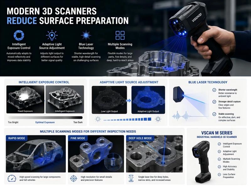
Fixed exposure settings may work well for uniform surfaces but become less effective when a component contains both dark and reflective areas. Intelligent exposure control helps compensate for these differences by adjusting data acquisition according to the amount of light returned from different regions of the part.
This is especially useful for mixed-material components, where black plastic, polished metal, painted surfaces, and machined areas may all appear within the same inspection task. Better exposure control can reduce overexposed regions, weak signals, and repeated rescanning.
Adaptive Light Source Adjustment Improves Data Capture
Light source adjustment also plays an important role in scanning difficult surfaces. By adapting light output to different surface conditions, the scanner can improve signal stability without requiring the operator to manually change settings for every area.
For industrial inspection, this can make direct scanning more practical for dark components, reflective metal parts, and surfaces with large differences in reflectivity.
Blue Laser Scanning Supports Challenging Industrial Surfaces
Blue laser technology is widely used in industrial 3D scanning because its shorter wavelength can provide stable feature capture and high-detail measurement for a range of manufacturing surfaces. When combined with suitable exposure control and optical adjustment, it can improve data acquisition on reflective, dark, and geometrically complex components.
The effectiveness of any scanning method still depends on the actual material, surface finish, geometry, and inspection environment, so extremely reflective or transparent parts may still require additional preparation.
Multiple Scanning Modes Help Capture Different Features
Surface condition is only one part of the scanning challenge. Part size and geometry also determine how efficiently complete data can be collected. A scanner with multiple acquisition modes allows operators to select a suitable approach for different inspection tasks.
- Rapid Mode: Suited for high-speed scanning of large components, full vehicles, and large sheet metal parts.
- Fine Mode: Designed to capture small geometric details and precision features where higher data resolution is required.
- Deep Hole Mode: Uses a single laser line to acquire data from narrow holes, recessed areas, and other difficult-to-reach geometries.
The industrial handheld 3D scanner VScan M Series combines intelligent exposure, light source adjustment, and multiple scanning modes to support direct measurement of components with different sizes, surface finishes, and geometric features. This helps reduce unnecessary surface preparation while maintaining flexibility for dimensional inspection and quality control.
Choosing the Right Approach for Different Surface Conditions
Different surface conditions create different optical challenges, so the same scanning strategy should not be applied to every part. The most effective approach depends on whether the main problem is excessive reflection, weak signal return, mixed materials, or difficult geometry.
| Surface Condition | Main Scanning Challenge | Recommended Approach |
|---|---|---|
| Polished Metal | Strong specular reflection and local overexposure | Reduce exposure, optimize scanning angle, and use surface treatment when necessary |
| Glossy Painted Surface | Uneven reflections across curved or coated areas | Use adaptive exposure and control surrounding light conditions |
| Black Plastic or Rubber | Low reflected signal caused by strong light absorption | Increase exposure or light intensity and use intelligent exposure control |
| Black and Reflective Areas on the Same Part | Large differences in surface reflectivity | Use adaptive exposure and light source adjustment to reduce repeated parameter changes |
| Mirror-Like or Highly Polished Surface | Extreme reflection that prevents stable direct data capture | Apply scanning spray or another temporary matte surface treatment when required |
| Deep Holes and Reflective Cavities | Restricted viewing angles combined with unstable reflected light | Use a dedicated deep-hole scanning mode and adjust the scanner position |
In practice, several of these conditions may appear on the same industrial component. A polished metal part, for example, may also contain deep holes, curved surfaces, and dark coated areas. For this reason, successful 3D scanning of reflective and black surfaces often requires a combination of exposure control, scanning angle adjustment, suitable scanning modes, and selective surface preparation rather than relying on a single technique.
Industrial Applications of Reflective and Black Surface 3D Scanning
Reflective and dark surfaces are common across many manufacturing sectors, especially where metal finishing, coatings, plastics, or complex geometries are involved. Reliable 3D scanning of these surfaces can support dimensional inspection, CAD comparison, reverse engineering, and quality control without relying solely on contact measurement methods.
Automotive Components
Automotive inspection often involves glossy body panels, stamped sheet metal, black plastic parts, coated components, and EV structures. These surfaces can vary greatly in reflectivity across the same assembly, making adaptive scanning particularly useful.
3D scanning can be used to inspect body panels, structural parts, battery-related components, and other automotive parts for dimensional deviation, surface accuracy, and manufacturing consistency.
CNC Machined and Precision Metal Parts
Machined aluminum, stainless steel, and other precision metal components frequently have reflective finishes that can interfere with optical data capture. Complex edges, small holes, and fine features can make measurement even more demanding.
With suitable exposure control and scanning strategies, 3D scanning can support dimensional verification, profile inspection, and CAD comparison for CNC parts and other precision-manufactured components.
Molds, Dies, and Tooling
Polished molds and dies often contain smooth reflective surfaces, deep cavities, narrow grooves, and complex freeform geometry. These features can make complete 3D data acquisition difficult if surface reflections are not properly managed.
Industrial 3D scanning allows manufacturers to evaluate mold geometry, wear, deformation, and deviation from CAD data while reducing the need for extensive point-by-point contact measurement.
Complex Industrial Components
Many industrial parts combine several challenging conditions at once, such as dark coatings, reflective metal, recessed areas, deep holes, and small geometric details. Examples include mechanical assemblies, cast components, tooling parts, and precision structures.
For these applications, flexible scanning modes and adaptive optical settings help capture more complete surface data for inspection, reverse engineering, and manufacturing quality control.
FAQ About 3D Scanning Reflective and Black Surfaces
Can a 3D scanner scan reflective metal?
Yes. Industrial 3D scanners can measure many reflective metal surfaces, but the results depend on surface finish, scanning technology, exposure settings, and measurement conditions. Polished or mirror-like metal may require exposure adjustment, changes in scanning angle, or temporary surface treatment to obtain stable and complete data.
Can you 3D scan black objects without scanning spray?
Many modern 3D scanners can capture black and dark surfaces without scanning spray by using stronger light sources, intelligent exposure control, and improved optical sensors. However, very dark or highly absorbent materials may still require additional adjustments or surface preparation depending on the required measurement accuracy.
Why do reflective surfaces cause missing 3D scan data?
Reflective surfaces can create strong specular reflections that either overload the scanner sensor or redirect projected light away from it. When the sensor receives too much or too little usable light, some areas may appear incomplete, noisy, or missing in the point cloud.
When should scanning spray be used?
Scanning spray is useful when direct scanning cannot produce stable data from mirror-like, highly polished, transparent, or extremely reflective surfaces. It creates a temporary matte coating that reduces unwanted reflections and improves optical data capture. Surface treatment should be selected according to the part material and required inspection accuracy.
Does scanning spray affect 3D measurement accuracy?
It can. Scanning spray adds a physical coating to the measured surface, so coating thickness and uniformity should be considered in high-accuracy dimensional inspection. For metrology applications with tight tolerances, a thin and consistent coating is particularly important.
What type of 3D scanner is suitable for black and reflective parts?
A suitable scanner should provide stable optical performance across different surface conditions, with features such as intelligent exposure control, adjustable light output, multiple scanning modes, and sufficient measurement accuracy. For parts with varied sizes, complex geometry, or difficult-to-access features, an industrial handheld 3D scanner can provide additional flexibility for on-site inspection and quality control.
Conclusion
Reflective and black surfaces can make optical 3D scanning more difficult, but the best solution depends on the material, surface finish, geometry, inspection environment, and required measurement accuracy. Exposure control, scanning angle, light source adjustment, suitable scanning modes, and selective surface preparation can all help improve data completeness and measurement stability.
Modern industrial 3D scanners are increasingly capable of handling challenging surfaces directly, reducing the need for repeated parameter adjustment or scanning spray in many applications. For components that combine dark materials, reflective finishes, deep holes, and complex geometry, flexible scanning technology can make dimensional inspection and quality control more efficient.
For manufacturers working with demanding industrial parts, selecting a 3D scanning solution with strong optical adaptability and multiple measurement modes can help achieve more reliable results across a wider range of surface conditions.