3D Scanning for Reverse Engineering: From Physical Part to CAD Model
Many manufacturers need to recreate, modify, or reproduce existing components when original CAD files, engineering drawings, or design documentation are unavailable. This situation is common for legacy parts, discontinued components, replacement parts, molds, tooling, and industrial equipment that has remained in service for many years.
3D scanning for reverse engineering provides an efficient way to capture the geometry of a physical part and convert it into accurate digital data for CAD reconstruction. Compared with traditional measurement methods that collect individual dimensions, 3D scanning can capture complex shapes, curved surfaces, and freeform features to create a more complete representation of the existing component.
However, reverse engineering is not simply the process of creating a digital copy of an object. The captured scan data must be processed, interpreted, and reconstructed into an editable CAD model that can support product redesign, replacement manufacturing, dimensional verification, and future engineering applications.
This article explains how 3D scanning supports the complete reverse engineering process, from capturing a physical part and generating digital geometry to reconstructing a reliable CAD model for industrial use.
When Is 3D Scanning Used for Reverse Engineering?
3D scanning is especially valuable when accurate geometric information needs to be recovered from an existing physical part. In many industrial applications, the original CAD model, engineering drawings, or design documentation may no longer be available, while the physical component still needs to be reproduced, modified, repaired, or digitally documented.
3D scanning for reverse engineering provides an efficient method to capture the geometry of an existing component and convert it into digital data for CAD reconstruction. Compared with traditional measurement methods that collect individual dimensions, 3D scanning can capture complex shapes, curved surfaces, and freeform features to create a more complete representation of the physical part.
The purpose of reverse engineering is not simply to create a digital copy of an object. The captured scan data must be processed, interpreted, and reconstructed into an editable CAD model that can support replacement manufacturing, product redesign, dimensional verification, and future engineering development.
Recovering Existing Components Without Original CAD Data
Many industrial components require reverse engineering because the original CAD files, engineering drawings, or technical documentation are no longer available. This situation is common for legacy parts, discontinued components, inherited machinery, and equipment that has remained in service for many years.
In these cases, 3D scanning can capture the existing geometry and provide the reference data needed to rebuild an engineering model. This approach is particularly useful when manually recreating complex curves, transitions, freeform surfaces, and detailed features through conventional measurement methods would be difficult or time-consuming.
However, existing components may contain wear, deformation, corrosion, or previous repairs after years of operation. During the reverse engineering process, engineers need to distinguish between the current physical condition of the part and the intended original geometry before creating the final CAD model.
Supporting Replacement Parts and Product Redesign
3D scanning is widely used when manufacturers need to develop replacement parts from an existing physical sample. The captured scan data provides a geometric reference for rebuilding important surfaces, mounting locations, interfaces, holes, and other functional features that must correctly match surrounding components.
The collected data can then be processed and reconstructed into an editable CAD model suitable for manufacturing preparation, redesign, or further engineering modification. Instead of rebuilding a component completely from the beginning, engineers can preserve existing geometry while improving selected areas or adapting the design for new requirements.
Digitizing Molds, Tooling, and Manufacturing Assets
Molds, dies, fixtures, and production tooling often contain complex surfaces that are difficult to recreate through traditional measurement methods. 3D scanning can capture both regular geometric features and freeform surfaces, providing detailed reference data for CAD reconstruction.
This approach is useful when original design files are missing, tooling has been modified during production, or manufacturers need to repair, duplicate, or update existing manufacturing assets.
Across these applications, the core objective remains the same: transform the geometry of a physical object into reliable digital information that can be reconstructed into an engineering-ready CAD model.
From Physical Part to CAD: The Reverse Engineering Workflow
A complete reverse engineering project involves more than capturing the surface of a component. The scanned data needs to be processed, reconstructed, and verified before it can become an engineering-ready CAD model.
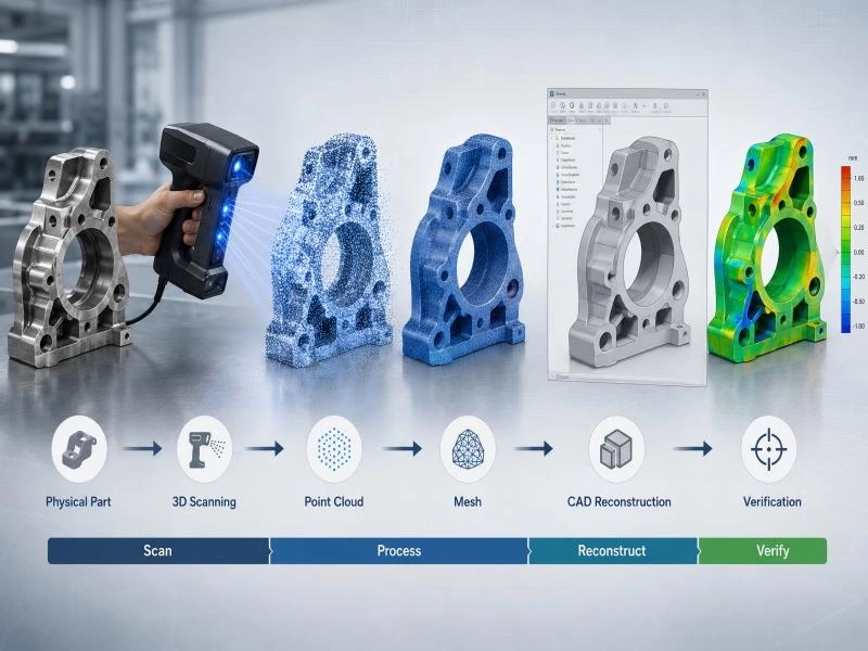
The typical workflow includes several stages:
- Physical part preparation and scanning
- Point cloud generation and alignment
- Mesh processing
- CAD reconstruction
- Final verification against scan data
Each stage affects the accuracy and usability of the final model. A complete 3D scan to CAD workflow should therefore be planned according to the part geometry, surface condition, required accuracy, and final engineering purpose.
Preparing and Capturing the Physical Part
Before scanning begins, engineers need to understand the purpose of the reverse engineering project...
Important factors include:
- Required measurement accuracy
- Critical functional features
- Surface condition and reflectivity
- Accessibility of complex areas
For components requiring flexible measurement from different angles, an industrial handheld 3D scanner can help capture complex surfaces and freeform geometry efficiently.
From Scan Data to CAD Reconstruction
After data acquisition, multiple scans are aligned into a unified coordinate system...
The process generally includes:
- Point cloud alignment and cleanup
- Mesh generation and surface processing
- Feature recognition
- CAD geometry reconstruction
The mesh provides a reference for the physical surface, while the final CAD model requires additional engineering interpretation to define editable features and design intent.
Mesh to CAD: Why Reconstruction Is More Than File Conversion
One of the most common misunderstandings in reverse engineering is assuming that a 3D scan can be directly converted into a complete CAD model. In reality, the transition from scanned data to engineering CAD requires additional reconstruction work. The purpose is not only to reproduce the surface of an existing part, but also to rebuild the geometry in a format that can support design changes, manufacturing, and further engineering analysis.
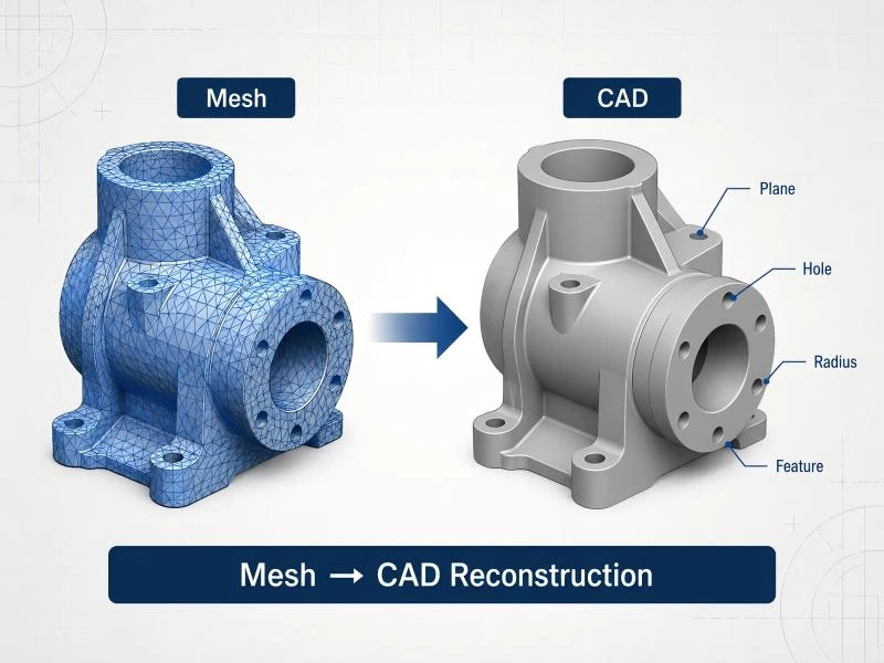
During a 3D scan to CAD workflow, the scanner first captures the physical surface as measured data. This data is then processed into a mesh representation before engineers reconstruct the final CAD model. Each stage represents a different type of digital information and serves a different purpose.
| Data Type | Main Purpose | Application |
|---|---|---|
| Point Cloud | Records measured points from the physical part | Data capture, alignment, and geometry reference |
| Mesh | Creates a polygon representation of the scanned surface | Surface visualization, STL export, and basic analysis |
| CAD Model | Defines editable engineering geometry | Design modification, manufacturing, and documentation |
A Mesh Represents the Existing Surface, Not the Engineering Design
A mesh is created by connecting measured scan points into a continuous polygon surface. It can accurately represent complex shapes, curved surfaces, and freeform geometry, making it useful for visualization and surface reference.
However, a mesh mainly describes what the scanner captured from the physical part. It does not automatically contain editable engineering features such as hole dimensions, reference planes, cylinders, fillets, design parameters, or functional relationships between different components.
For this reason, a mesh file such as STL or OBJ may be suitable for certain applications, but it is usually not enough when engineers need to modify the design, reproduce the part, or prepare it for manufacturing.
CAD Reconstruction Recovers Usable Engineering Geometry
Converting scan data into a CAD model requires engineers to interpret the measured geometry and rebuild the features that define the component. This process may include identifying:
- Planes and reference surfaces
- Cylindrical features and holes
- Slots, edges, and mounting areas
- Fillets and curved transitions
- Freeform surfaces and complex profiles
For mechanical components, the reconstructed model is often created as parametric CAD geometry so that important dimensions and features can be adjusted later. For parts with complex surfaces, such as molds, automotive components, or industrial products, surface reconstruction may be required to create smooth and accurate CAD surfaces.
Reverse Engineering Requires Engineering Interpretation
The goal of CAD reconstruction is not always to copy every small variation captured by the scanner. Physical parts may contain manufacturing tolerances, wear, deformation, or surface damage that should not become part of the final engineering model.
Engineers need to evaluate which features represent the intended design and which differences are caused by the current condition of the part. This is especially important when reconstructing replacement components or modifying existing products.
A reliable reverse engineering CAD reconstruction process therefore combines accurate scan data with engineering knowledge. The scanner provides a detailed reference of the physical object, while CAD reconstruction transforms that information into a usable digital model.
Matching the CAD Model to the Final Application
The required level of reconstruction depends on how the final model will be used. A reference model for visualization may only require a cleaned mesh, while a production-ready component requires editable CAD geometry with accurate dimensions and functional features.
Common applications include:
- Replacement part manufacturing
- Product redesign and modification
- Mold and tooling reconstruction
- Legacy component digitization
- Engineering documentation updates
Understanding the difference between scanned data, mesh models, and CAD geometry is essential for achieving reliable results in reverse engineering projects. The final objective is not simply to convert files, but to create a digital model that can support real engineering decisions.
Reconstructing Design Intent from an Existing Part
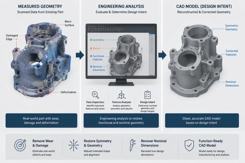
In reverse engineering projects, the purpose of 3D scanning is not always to copy the existing physical condition of a component. A scanned part may already contain wear, deformation, corrosion, repairs, or manufacturing variation caused by long-term use. Therefore, creating an accurate CAD model requires engineers to understand the original design intent behind the measured geometry.
The scanner captures what the part currently looks like, while the reverse engineering process determines how that information should be interpreted for redesign, reproduction, or manufacturing. This difference is especially important when working with legacy components or replacement parts that have been used for many years.
Distinguishing Original Geometry from Wear and Deformation
Physical parts often change during their service life. Mechanical contact, repeated loading, environmental conditions, and previous repairs can all affect the measured surface.
For example, a worn shaft or enlarged mounting hole may appear clearly in the scan data, but directly reproducing these changes in CAD could create a model that reflects damage rather than the original engineering design.
During CAD reconstruction, engineers need to evaluate whether measured differences represent:
- Normal manufacturing variation
- Service-related wear
- Accidental damage or deformation
- Intentional design features
This evaluation helps ensure that the final CAD model represents the required functional geometry instead of simply duplicating the current condition of the part.
Using Symmetry and Geometric Relationships as References
Many industrial components contain design relationships that can help recover missing or altered geometry. Symmetry, repeated features, alignment references, and standard geometric elements provide important clues during reconstruction.
Common references include:
| Reference Feature | Purpose in Reconstruction |
|---|---|
| Symmetrical surfaces | Help restore damaged or missing areas |
| Mounting holes and patterns | Define functional positioning and assembly relationships |
| Cylindrical or planar features | Provide geometric references for CAD modeling |
| Mating surfaces | Ensure compatibility with connected components |
Using these references allows engineers to create a CAD model that follows the intended design structure rather than reproducing small inconsistencies from the scanned object.
Considering Functional Requirements During Reconstruction
A reverse-engineered component usually needs to work with other parts in an assembly. For this reason, functional areas such as mounting locations, sealing surfaces, connection points, and mechanical interfaces often require more attention than cosmetic surface variations.
Engineers may combine scan data with existing components, known dimensions, assembly requirements, or manufacturing standards to determine the correct geometry for the final CAD model.
This approach is particularly important for replacement parts, where the goal is not only to recreate the appearance of the original component but also to ensure proper installation and reliable operation.
Preserving Important Freeform Surfaces
Not all reverse engineering tasks involve simple mechanical geometry. Components such as automotive panels, molds, industrial housings, and designed surfaces may rely on complex curves and freeform shapes that need to be accurately maintained.
For these applications, engineers need to balance two requirements: preserving the original surface characteristics while removing unwanted noise, defects, or local deformation that does not represent the intended design.
Verify the Reconstructed Model Against Scan Data
After the design intent has been considered and the CAD model has been reconstructed, the final geometry should be compared with the original scan data.
This verification process helps identify whether differences between the CAD model and the physical part are caused by intentional design corrections or reconstruction errors. It provides confidence that the final model can be used for manufacturing, redesign, or further engineering applications.
Successful reverse engineering CAD reconstruction requires both accurate measurement data and engineering judgment. The goal is not simply to copy the scanned surface, but to create a digital model that reflects the intended function and purpose of the original component.
Factors That Affect Scan-to-CAD Accuracy
The accuracy of a reverse-engineered CAD model depends on more than the specification of the 3D scanner. Data acquisition, surface condition, scanning strategy, alignment, processing methods, and CAD reconstruction techniques can all influence the final result.
For this reason, scan-to-CAD accuracy should be evaluated across the complete reverse engineering workflow rather than only focusing on the scanning stage. A high-quality scan provides the foundation, but every step after data capture also affects the reliability of the final CAD model.
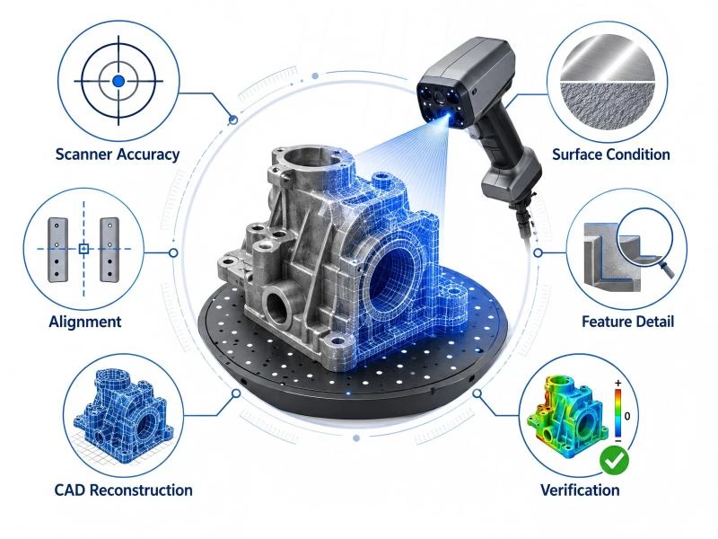
Scanner Accuracy and Measurement Requirements
The required scanner accuracy depends on the intended application of the reconstructed model. A component used for general shape reference may require a different level of precision compared with a replacement part, tooling component, or mechanical assembly with strict dimensional requirements.
Before scanning begins, engineers should define the critical requirements, including:
- Required measurement accuracy
- Important functional features
- Final CAD application
- Manufacturing or assembly requirements
Clearly defining these requirements helps avoid collecting insufficient data or spending additional time capturing unnecessary details.
Surface Condition and Material Characteristics
The surface condition of a physical part can directly affect optical data acquisition. Reflective metals, black surfaces, transparent materials, dirt, oil, and damaged coatings may influence how accurately the scanner captures the geometry.
In these situations, scanning parameters, surface preparation methods, and acquisition strategies should be selected according to the actual component. The objective is to obtain stable and complete scan data while preserving the original condition of the part whenever possible.
For complex surfaces, especially components with different material areas or varying reflectivity, maintaining consistent data quality is important for later CAD reconstruction.
Feature Details and Functional Geometry
In many reverse engineering projects, the most important areas are not always the largest surfaces. Small but functional features such as holes, edges, mounting points, grooves, and connection interfaces often determine whether the reconstructed CAD model can be used successfully.
During scanning, engineers should pay particular attention to areas that affect the function of the component:
- Mounting and assembly interfaces
- Precision holes and openings
- Contact surfaces
- Critical edges and profiles
A visually complete scan does not always guarantee a usable CAD model if important engineering features are not captured clearly.
Hidden Areas and Complex Geometry
Deep holes, narrow cavities, undercuts, and recessed areas can create challenges during data acquisition because some surfaces may not be directly visible from normal scanning angles.
For complex components, multiple scanning positions or different acquisition methods may be required to obtain complete geometric information. Missing data in functional areas can create uncertainty during CAD reconstruction and may require additional assumptions later in the process.
Scan Alignment and Data Processing
Large or complex parts are usually scanned from multiple directions. These individual scans must be accurately aligned into a common coordinate system before the data can be used for reconstruction.
Small alignment errors can accumulate across large components and affect overall dimensions, surface relationships, and feature positions. Proper registration and data processing are therefore essential parts of maintaining reliable 3D scan to CAD workflow accuracy.
After alignment, unnecessary data may be removed and the scan surface may be processed to improve usability. However, excessive filtering or smoothing should be avoided because important geometric details can be unintentionally modified.
CAD Reconstruction Method
The method used to rebuild the CAD model also has a significant impact on the final result. Different components require different reconstruction approaches depending on their geometry and intended application.
| Component Type | Common Reconstruction Approach |
|---|---|
| Mechanical Parts | Parametric features such as planes, cylinders, holes, and dimensions |
| Freeform Components | Surface reconstruction based on scanned geometry |
| Replacement Parts | Combination of measured data and engineering design intent |
Automatically fitting CAD geometry to every measured variation may reproduce wear or manufacturing differences that are not part of the original design. A successful reconstruction process requires both accurate scan data and engineering interpretation.
Final Verification Against Original Scan Data
After CAD reconstruction is completed, the model should be compared with the original scan data to confirm that the final geometry meets the required expectations.
Verification can help identify:
- Surface deviations
- Dimensional differences
- Incorrect feature reconstruction
- Areas requiring further adjustment
By verifying the reconstructed CAD model before manufacturing or redesign, engineers can reduce the risk of downstream errors and ensure that the final digital model accurately supports its intended application.
Reverse Engineering Different Types of Parts
The reverse engineering process varies depending on the size, complexity, and functional requirements of the component. Small precision parts, medium-sized industrial components, and large structures each present different challenges during scanning and CAD reconstruction.
Small Precision Components
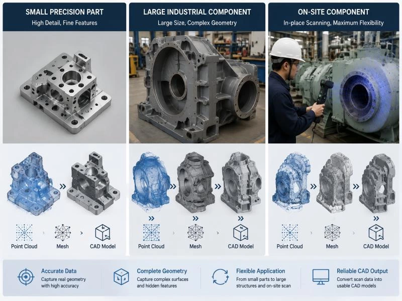
Small mechanical components often contain detailed features such as narrow slots, holes, edges, grooves, and complex interfaces. For these applications, capturing fine geometry and maintaining measurement accuracy are usually more important than scanning speed.
A professional handheld 3D scanner can support reverse engineering tasks that require detailed surface capture and accurate reconstruction of small or complex components.
Large Industrial Components
Large components such as machinery parts, molds, automotive structures, and industrial equipment require efficient surface coverage and reliable alignment between multiple scanning positions.
For these applications, scanning efficiency becomes increasingly important because incomplete or inconsistent data can affect the final CAD reconstruction. A high-efficiency handheld 3D scanner can help capture larger surfaces while maintaining the flexibility needed for complex industrial parts.
On-Site and Difficult-to-Move Components
Some components cannot be easily transported to a dedicated measurement environment. Heavy machinery, installed equipment, production-line components, and large tooling often require reverse engineering directly at the operating location.
In these situations, portability and measurement flexibility become important factors. A wireless handheld 3D scanner can provide greater freedom when capturing parts that are difficult to move or access.
Regardless of component size, the scanning strategy should always be determined by the final CAD requirements, including accuracy, feature details, accessibility, and intended engineering application.
Common Reverse Engineering Applications
3D scanning for reverse engineering is widely used in industries where physical components need to be digitized, reconstructed, modified, or reproduced. The technology is especially valuable when original CAD files are unavailable, outdated, or no longer represent the current engineering requirements.
By converting physical parts into accurate digital models, manufacturers can support replacement part development, product improvement, tooling updates, and long-term equipment maintenance without rebuilding every component from the beginning.
Legacy and Discontinued Parts
Many industrial systems remain in operation for decades, even when the original components, suppliers, or design documentation are no longer available. For these legacy parts, reverse engineering provides a practical method to recover the required geometry and create updated digital records.
3D scanning can capture complex surfaces, interfaces, and structural features from existing components, allowing engineers to reconstruct CAD models for repair, reproduction, or future manufacturing.
This approach is commonly used for older machinery, industrial equipment, transportation systems, and other long-life assets where replacing the entire system may not be practical.
Replacement Part Development
When a replacement component is needed but the original CAD data is missing, an existing physical sample can become the reference for new part development. Scan data provides accurate information about external geometry, mounting locations, holes, interfaces, and other important features.
After reconstruction, the CAD model can be adjusted according to manufacturing requirements, restored to nominal dimensions, or modified to improve performance and compatibility.
The workflow helps manufacturers reduce dependence on outdated drawings while creating a reliable digital foundation for replacement production.
Mold, Tooling, and Manufacturing Asset Reconstruction
Molds, dies, fixtures, and production tooling often contain complex surfaces that are difficult to reproduce through traditional measurement methods. Changes made during production, repairs, or long-term use can also cause the original design information to become incomplete.
3D scanning allows manufacturers to capture the current condition of these assets and use the data for CAD reconstruction, tooling repair, duplication, or process improvement.
- Mold surface reconstruction
- Fixture and jig digitization
- Tooling modification
- Existing manufacturing asset updates
Product Redesign and Engineering Modification
Reverse engineering is not always intended to create an identical copy of an existing component. In many cases, engineers use scanned data as a starting point for improving or modifying an existing design.
The reconstructed CAD model allows designers to analyze the original geometry, adjust selected features, add new functions, or adapt the component for a different application while preserving important existing characteristics.
This approach is useful for product upgrades, customized solutions, performance improvements, and design changes based on proven physical components.
Automotive and Industrial Components
Automotive parts, machinery components, and industrial structures often contain complex surfaces and functional interfaces that require accurate digital reconstruction.
Common applications include:
- Automotive body panels and interior components
- Mechanical housings and castings
- Industrial equipment components
- Custom or modified production parts
For these applications, 3D scanning helps capture the geometry of existing components and provides the digital data required for CAD modeling, redesign, and manufacturing preparation.
Across different industries, the value of reverse engineering lies in transforming physical objects into usable digital assets. A properly reconstructed CAD model can support current engineering needs while preserving important design information for future development.
Common Mistakes in Scan-to-CAD Reverse Engineering
A successful scan-to-CAD workflow depends not only on accurate scanning but also on how the collected data is interpreted and reconstructed. Several common mistakes can reduce the quality of the final CAD model even when the original scan data is complete.
Treating the Mesh as the Final CAD Model
A mesh accurately represents the scanned surface, but it is not automatically an editable engineering model. Polygon files such as STL or OBJ describe surface geometry but usually do not contain parametric features, design relationships, or editable dimensions.
For manufacturing, redesign, or engineering modification, the mesh should be treated as a reference for CAD reconstruction rather than the final product.
Ignoring the Required Accuracy Before Scanning
Another common mistake is collecting scan data without clearly defining the final application. Different projects require different levels of accuracy, detail, and reconstruction effort.
A model created for visual reference does not require the same requirements as a replacement component or precision mechanical part. Defining the purpose of the final CAD model before scanning helps determine the correct data acquisition strategy.
Reproducing Wear Instead of Original Design
Existing parts may contain wear, deformation, corrosion, or previous repairs. Directly copying every measured variation into the CAD model may reproduce the damaged condition rather than the intended design.
Engineers should evaluate functional requirements, symmetry, mating relationships, and original design intent before deciding which scanned features should be retained or adjusted.
Skipping Functional Features and Final Verification
External appearance alone is not always enough for successful reverse engineering. Hidden areas, mounting interfaces, sealing surfaces, holes, and connection features may determine whether the final component can function correctly.
After CAD reconstruction, the model should also be compared with the original scan data to verify dimensions, surfaces, and critical features before manufacturing or redesign begins.
A reliable reverse engineering process requires more than capturing geometry. Accurate scanning, proper data processing, engineering interpretation, and final verification are all necessary to create a CAD model that can be confidently used in real industrial applications.
FAQ About 3D Scanning for Reverse Engineering
Can you create an editable CAD model from a 3D scan?
Yes. A 3D scan can provide the geometric reference needed to create an editable CAD model, but the scan data itself is not automatically a complete engineering model.
The typical process includes capturing the physical part, generating scan data, processing the point cloud or mesh, and reconstructing CAD geometry with editable features such as dimensions, surfaces, holes, and design relationships.
The level of reconstruction depends on the final application. A reference model may require less processing, while a production-ready replacement part usually requires a more detailed CAD reconstruction process.
What is the difference between a 3D scan, mesh, and CAD model?
A 3D scan records measured information from the physical component. The captured data is usually represented as a point cloud containing the coordinates of the scanned surface.
A mesh connects these points into a polygon surface that represents the shape of the scanned object. It is commonly used for visualization, surface reference, and some manufacturing applications.
A CAD model goes further by rebuilding the geometry into editable engineering features. Unlike a mesh, a CAD model can contain parameters, dimensions, and design features that support modification, manufacturing, and future engineering work.
How accurate is 3D scanning for reverse engineering?
The accuracy of 3D scanning for reverse engineering depends on multiple factors, including scanner performance, part size, surface condition, scanning strategy, data alignment, and CAD reconstruction methods.
A reliable result requires controlling accuracy throughout the entire scan-to-CAD process rather than evaluating only the scanner specification. The final CAD model should be verified against the original scan data to confirm that important dimensions and features meet the required requirements.
Can worn or damaged parts be reverse engineered?
Yes. Worn or damaged parts can still be used as references for reverse engineering. However, the scanned geometry should not always be copied directly into the final CAD model.
Engineers may need to identify which areas represent the original design and which areas have changed due to wear, deformation, corrosion, or previous repairs. The goal is to reconstruct the intended functional geometry rather than reproduce unwanted damage.
Can large industrial parts be converted from 3D scan to CAD?
Yes. Large industrial components such as machinery parts, molds, tooling, automotive structures, and production equipment can be converted from 3D scan data into CAD models.
Large-part reverse engineering usually requires careful planning because multiple scanning positions, data alignment, and complete surface coverage are important factors in maintaining reliable geometry throughout the reconstruction process.
What file formats are commonly used in a scan-to-CAD workflow?
Common scan data formats include STL, OBJ, PLY, and other point cloud or mesh-based formats. These files are typically used as references during surface processing and CAD reconstruction.
After reconstruction, the final CAD model may be exported in engineering formats such as STEP, IGES, or native CAD formats depending on the requirements of design, manufacturing, and downstream engineering software.
Conclusion
3D scanning for reverse engineering provides an efficient method for transforming existing physical components into usable digital engineering models. When original CAD files or technical documentation are unavailable, 3D scanning can capture complex geometry and provide the foundation for CAD reconstruction.
However, successful reverse engineering involves more than collecting scan data. The complete process requires accurate data acquisition, proper processing, engineering interpretation, CAD reconstruction, and final verification.
The workflow can be summarized as: physical part → 3D scan → point cloud or mesh → CAD reconstruction → verification. By combining accurate measurement data with engineering knowledge, manufacturers can create reliable CAD models for replacement parts, product redesign, tooling reconstruction, and other industrial applications.