What Is Photogrammetry? How It Works in Industrial 3D Scanning
Photogrammetry is a measurement technique that uses multiple images captured from different positions to calculate the three-dimensional coordinates, dimensions, and spatial relationships of an object. By identifying common features or measurement targets across different images, photogrammetry can reconstruct accurate 3D information without requiring direct contact with the measured part.
In industrial measurement, photogrammetry is especially useful when working with large components, long measurement spans, or complex structures that require consistent dimensional relationships across the entire object. Applications may include full vehicles, aerospace structures, large castings, heavy machinery components, and industrial tooling.
Unlike conventional photography, which mainly records appearance, industrial photogrammetry focuses on extracting measurable spatial information. It can establish a global coordinate reference across a large measurement volume, providing a stable foundation for dimensional analysis and other 3D measurement tasks.
Photogrammetry can also complement industrial 3D scanning. While a 3D scanner captures dense surface geometry and fine features, photogrammetry can provide a broader global reference for positioning scan data over large areas. This combination is particularly valuable when multiple scanning positions are required and overall dimensional accuracy must be maintained across the complete component.
This article explains what photogrammetry is, how it works, what affects photogrammetry accuracy, how it differs from 3D scanning, and why it is increasingly used for large-scale industrial 3D measurement.
How Does Photogrammetry Work?
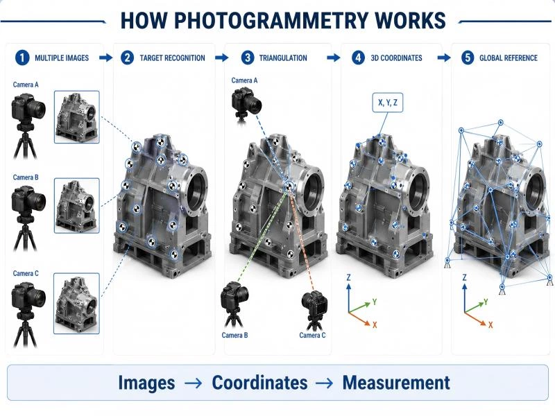
Photogrammetry works by comparing multiple images of the same object captured from different positions. When the same target or feature appears in several photographs, its location can be calculated from the different viewing angles. Repeating this process across many reference points creates a three-dimensional coordinate network that represents the spatial relationships across the measured object.
In industrial measurement, the process usually follows a structured sequence:
- Capture images from multiple positions around the component
- Identify common targets or recognizable features in different images
- Calculate their 3D coordinates through triangulation
- Combine the coordinates into a global measurement network
- Use the resulting reference system for dimensional measurement or additional 3D scanning
Capture Images from Multiple Positions
The first step is to photograph the component from different locations and viewing angles. Each image provides a different line of sight to the same measurement targets or surface features.
Good image coverage is important because each target should ideally appear in several photographs. Capturing the object from different directions provides the geometric information required for accurate coordinate calculation.
For large industrial components, image acquisition may extend around the entire workpiece so that the resulting measurement network covers the full measurement volume rather than only a local area.
Identify Common Targets or Features
Photogrammetry software then identifies corresponding points that appear across multiple images. In industrial applications, coded targets or measurement markers are often used because they provide clear and repeatable reference points.
These targets help the system establish relationships between different images and determine which observations correspond to the same physical location on the component.
Common reference information may include:
- Coded measurement targets
- Reference markers
- Scale information
- Recognizable geometric features
Calculate 3D Coordinates Through Triangulation
Once corresponding points have been identified, the system calculates their positions using triangulation. A target observed from different camera positions creates multiple lines of sight, and their geometric relationship can be used to determine the target's location in three-dimensional space.
The accuracy of this calculation depends on factors such as camera calibration, image geometry, target distribution, and the number of observations available for each point.
Rather than relying on a single photograph, photogrammetry combines information from many images to create a more stable estimate of the spatial coordinates.
Build a Global Measurement Network
After the target coordinates have been calculated, the system creates a common coordinate framework covering the measured component. This global network defines the relative positions of reference points across the entire measurement area.
For small objects, this may simply provide dimensional information between several features. For large industrial structures, the global reference becomes especially valuable because it helps maintain consistent spatial relationships across long measurement distances.
| Photogrammetry Stage | Measurement Purpose |
|---|---|
| Image Capture | Observe the same object or targets from multiple positions |
| Target Recognition | Match corresponding reference points across different images |
| Triangulation | Calculate three-dimensional target coordinates |
| Global Network | Establish a unified spatial reference across the measurement volume |
This global coordinate network is one of the key reasons photogrammetry is valuable in industrial measurement. It provides a large-scale reference framework that can later be combined with detailed 3D scanning data when both overall dimensional relationships and fine surface geometry are required.
What Is 3D Photogrammetry?
3D photogrammetry refers to the use of photographic images to calculate three-dimensional spatial information about an object or measurement area. By analyzing the same targets or features from multiple viewing positions, the system can determine their coordinates and build a measurable 3D representation.
In industrial applications, 3D photogrammetry is commonly used to establish accurate spatial relationships across large components. Rather than focusing primarily on dense surface detail, it provides a stable coordinate framework that helps define the overall size, position, and geometry of the measured object.
From Image Data to 3D Coordinates
The transition from ordinary photographs to measurable 3D data depends on identifying the same reference points across multiple images. Once their positions are calculated, the resulting coordinates can be organized into a measurement network that represents the geometry of the object in three-dimensional space.
Typical outputs may include:
- 3D coordinates of measurement targets
- Distances between reference points
- Relative position of different component areas
- Large-scale dimensional relationships
- A global coordinate framework for additional measurement
These outputs are especially useful when the component is too large to be measured efficiently from a single position or when different measurement areas need to remain within one consistent coordinate system.
3D Photogrammetry Does Not Always Mean Dense Surface Capture
One important distinction is that 3D photogrammetry does not necessarily produce the same type of dense surface data as a 3D scanner. In industrial metrology, photogrammetry may focus primarily on accurately locating targets distributed across the component rather than recording every surface contour.
| Data Type | Main Purpose |
|---|---|
| Photogrammetric Coordinates | Establish global positions and dimensional relationships across a large measurement area |
| Dense 3D Scan Data | Capture detailed surface geometry, edges, holes, and freeform features |
This difference is important in large-scale industrial measurement. Photogrammetry can provide the overall coordinate reference, while detailed 3D scanning can be used where dense surface information is required.
Why 3D Photogrammetry Is Valuable in Industrial Measurement
As the size of a component increases, maintaining accurate relationships between distant measurement areas becomes more important. Large automotive structures, aerospace assemblies, industrial tooling, and heavy machinery may require measurements across several meters rather than within a small local region.
In these situations, 3D photogrammetry can create a global reference network before detailed surface measurement begins. Different scan regions can then be related to the same coordinate framework, helping preserve overall dimensional consistency across the complete component.
This ability to combine large-scale spatial reference with detailed measurement is one of the main reasons 3D photogrammetry is widely used alongside industrial 3D scanning for large-part measurement.
How Accurate Is Photogrammetry?
The accuracy of photogrammetry depends on how the images are captured, calibrated, and processed. Unlike a fixed measurement specification that applies to every project, photogrammetric accuracy varies with the measurement setup, object size, target distribution, camera geometry, and environmental conditions.
For industrial applications, accuracy should therefore be evaluated across the complete measurement volume rather than judged only by image resolution or camera specifications.
Key Factors That Affect Photogrammetry Accuracy
Several factors influence how reliably image observations can be converted into three-dimensional coordinates:
- Camera or Sensor Resolution: Higher image detail can improve target recognition and coordinate calculation when the measurement setup is properly configured.
- Camera Calibration: Accurate calibration helps correct optical distortion and supports reliable geometric calculations.
- Target Distribution: Measurement targets should be distributed across the component so the system can establish stable spatial relationships throughout the measurement area.
- Image Geometry: Capturing targets from multiple positions and viewing angles improves triangulation quality.
- Measurement Volume: Larger measurement ranges generally require greater attention to global accuracy and reference stability.
- Environmental Conditions: Temperature changes, vibration, lighting, and movement can influence measurement consistency.
Image Geometry Is as Important as Image Quantity
Taking more photographs does not automatically guarantee better results. The geometry of those images is equally important. If all images are captured from similar positions or angles, the system may have limited geometric information for triangulation.
A more reliable photogrammetry setup observes the same targets from different directions and provides sufficient overlap across the complete measurement area. This creates stronger geometric relationships between the images and improves the stability of the calculated coordinates.
| Measurement Condition | Potential Effect on Accuracy |
|---|---|
| Well-distributed targets | Improves global coordinate stability across the component |
| Multiple viewing angles | Provides stronger triangulation geometry |
| Poor target coverage | May reduce reliability in some measurement regions |
| Large unsupported measurement spans | Can increase uncertainty in overall dimensional relationships |
Industrial Photogrammetry vs General-Purpose Photogrammetry
General-purpose photogrammetry may be used to create 3D models for visualization, mapping, or documentation, where geometric appearance can be more important than metrology-level dimensional reliability.
Industrial photogrammetry systems place greater emphasis on calibrated measurement, controlled targets, scale references, and repeatable coordinate calculation. These characteristics make them more suitable for applications where the resulting data will be used for dimensional inspection or large-scale industrial measurement.
Why Accuracy Matters More for Large Components
For small objects, local geometric accuracy may be sufficient for many measurement tasks. Large components create a different challenge because distant regions must remain dimensionally consistent within the same coordinate framework.
When measuring full vehicles, aircraft structures, large castings, tooling, or heavy machinery, even small local alignment differences can become more significant across long measurement spans. This is why photogrammetry is particularly valuable when maintaining a stable global reference is essential.
Rather than relying on a universal accuracy value, manufacturers should evaluate photogrammetry accuracy according to the measurement volume, required tolerance, target arrangement, calibration method, and final inspection purpose.
Photogrammetry vs 3D Scanning: What Is the Difference?
Photogrammetry and 3D scanning can both produce three-dimensional measurement data, but they capture information in different ways and are typically used for different measurement tasks. Photogrammetry is particularly effective at establishing large-scale spatial relationships, while 3D scanners are designed to capture dense surface geometry and detailed features.
For industrial measurement, the two technologies should not always be viewed as alternatives. On large components, they can complement each other by combining a stable global reference with detailed surface data.
| Comparison | Photogrammetry | 3D Scanning |
|---|---|---|
| Measurement Principle | Uses multiple images and triangulation to calculate 3D coordinates | Uses laser or optical projection to capture surface geometry |
| Primary Data | Global coordinates and spatial relationships | Dense point cloud and detailed surface geometry |
| Measurement Range | Well suited to large measurement volumes and long distances | Well suited to detailed measurement of local and complete surfaces |
| Surface Detail | Generally not the main objective in industrial metrology | Captures holes, edges, contours, and freeform surfaces in detail |
| Typical Role | Provides a global measurement reference | Provides detailed geometric measurement data |
| Large-Part Measurement | Helps maintain consistent dimensional relationships across the complete component | Captures detailed geometry from multiple scanning positions |
Photogrammetry Focuses on Global Spatial Relationships
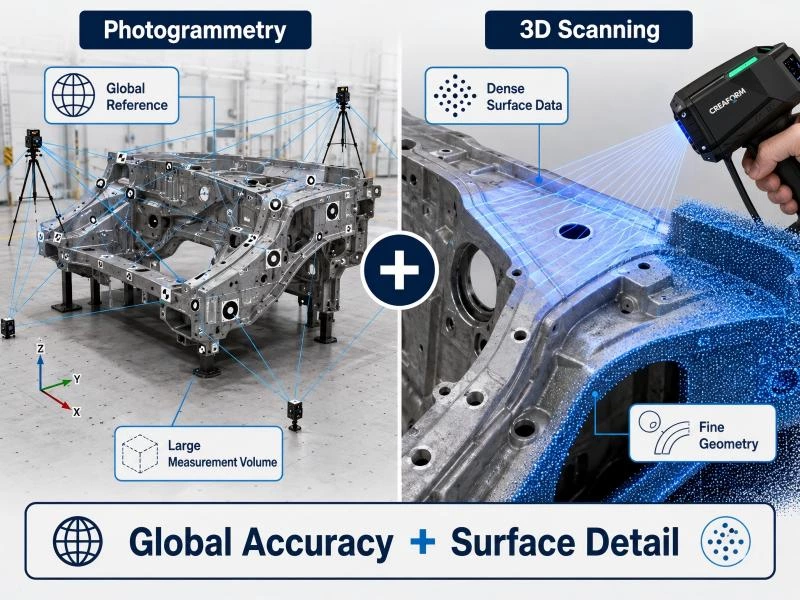
One of the main strengths of photogrammetry is its ability to establish reference coordinates over a large measurement area. Targets distributed across a component can be observed from multiple camera positions and calculated within the same coordinate framework.
This makes photogrammetry particularly useful when the measurement task involves long distances between features, large structures, or components that require data capture from many different positions.
3D Scanning Captures Dense Surface Geometry
A 3D scanner captures a much denser representation of the component surface. Depending on the scanning technology, millions of measurement points can be collected to reproduce detailed geometry, including complex curves, edges, holes, freeform surfaces, and local dimensional features.
This dense data is valuable for applications such as dimensional inspection, CAD comparison, deformation analysis, and reverse engineering, where understanding the actual surface shape is essential.
Photogrammetry and 3D Scanning Can Work Together
For large industrial components, a combined measurement approach can provide advantages that either technology alone may not offer as efficiently. Photogrammetry can first establish a global coordinate network across the complete component, while a 3D scanner captures detailed surface information in individual measurement areas.
The resulting workflow can be summarized as:
Photogrammetry → Global Reference → 3D Scanning → Dense Surface Data → Complete Measurement
This approach is especially useful for full vehicles, large castings, aerospace structures, heavy machinery, and other components that require both long-range dimensional consistency and high-resolution surface measurement.
In these applications, the question is therefore not always photogrammetry vs 3D scanning. The more important consideration is how the two technologies can be combined to achieve reliable large-scale measurement while preserving detailed geometric information.
Why Is Photogrammetry Useful for Large-Part 3D Scanning?
Large-part 3D scanning introduces a different measurement challenge from scanning small or medium-sized components. The main difficulty is not only capturing enough surface detail, but also maintaining accurate dimensional relationships across a much larger measurement volume.
Components such as full vehicles, aircraft structures, large castings, machine frames, and industrial tooling often need to be scanned from multiple positions. As the scanner moves around the object, each local scan must remain correctly related to every other area of the component.
Large Measurement Volumes Require a Stable Global Reference
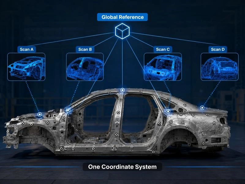
A 3D scanner usually captures only part of a large component at one time. To build a complete digital model, the operator may need to scan one area, move to another position, and continue capturing additional sections until the entire object is covered.
For example, a large industrial component may require:
- Multiple scanner positions around the workpiece
- Repeated data alignment between neighboring scan areas
- Measurement across several meters
- Consistent relationships between distant features
- Stable coordinates throughout the complete scanning process
When the measurement range becomes larger, maintaining this overall dimensional consistency becomes increasingly important.
Multiple Scan Positions Can Increase Alignment Challenges
Without a stable global reference, large objects may rely heavily on local alignment between adjacent scan areas. Each section is matched with the next based on overlapping geometry, markers, or other registration information.
A simplified workflow may look like:
Scan Area 1 → Scan Area 2 → Scan Area 3 → Scan Area 4
For shorter measurement distances, this approach can work effectively. However, as more scan positions are added, small local registration differences may become more significant across the complete measurement span.
This does not necessarily mean that the individual scan data is inaccurate. The challenge is maintaining the correct overall relationship between areas that may be several meters apart.
Photogrammetry Establishes a Global Coordinate Network
Photogrammetry helps address this challenge by creating a global reference before or during detailed 3D scanning. Measurement targets distributed across the large component are observed from multiple camera positions and calculated within one coordinate system.
The resulting structure can be represented as:
Global Reference → Scan Area A / Scan Area B / Scan Area C / Scan Area D
Instead of relying only on one scan area to define the position of the next, different regions can be related back to the same global coordinate network.
| Large-Part Measurement Challenge | How Photogrammetry Helps |
|---|---|
| Large measurement span | Creates a coordinate reference across the full component |
| Multiple scanner positions | Provides common reference points for different scan areas |
| Distant features must remain dimensionally consistent | Maintains their spatial relationships within one global network |
| Complex or difficult-to-move structures | Supports flexible measurement from multiple positions on site |
Global Accuracy and Local Detail Can Be Combined
The main advantage of photogrammetry in large-part 3D scanning is that it addresses a different level of the measurement problem. Photogrammetry focuses on the global position and relationship of measurement areas, while the 3D scanner captures detailed local surface geometry.
For a large casting, for example, photogrammetry can establish reference points across the entire structure. The scanner can then capture detailed surfaces, holes, mounting features, edges, and freeform geometry in individual regions while keeping those regions connected to the same overall reference.
This combination is particularly useful when manufacturers need both detailed surface information and reliable long-range dimensional relationships. For large industrial components, photogrammetry therefore becomes an important supporting technology for more stable and accurate large-part 3D scanning.
How Photogrammetry Works with a 3D Scanner
Photogrammetry and 3D scanning can be combined when a measurement task requires both large-scale spatial accuracy and detailed surface geometry. Instead of asking one technology to perform both roles, the workflow assigns each system to the type of measurement it handles best.
Photogrammetry establishes a global coordinate framework across the complete component, while the 3D scanner captures dense geometric data from individual areas. The scan data can then be aligned within the photogrammetric reference so that detailed local measurements remain consistent across the full measurement volume.
Photogrammetry Provides the Global Reference
Before detailed scanning begins, measurement targets can be distributed across the component and captured from multiple camera positions. The photogrammetry system calculates the 3D coordinates of these targets and creates a global measurement network.
This reference defines the spatial relationships between different parts of the object, including areas that may be several meters apart. For large structures, the global coordinate network helps reduce dependence on repeated local alignment alone.
- Establishes reference coordinates across the complete component
- Maintains relationships between distant measurement areas
- Supports measurement across large volumes
- Provides common reference points for multiple scan positions
The 3D Scanner Captures Dense Surface Geometry
Once the global reference has been established, a 3D scanner can be used to capture detailed geometry from the component surface. Unlike photogrammetry, which may rely on a network of measurement targets, the scanner collects dense point data that describes the actual shape of the part.
This detailed information can include:
- Freeform surfaces
- Edges and contours
- Mounting holes
- Machined features
- Local deformation
- Complex geometric details
A metrology-grade handheld 3D scanner can move around large or complex components and capture detailed surface data from multiple positions while using the photogrammetric reference to maintain overall spatial consistency.
Combining Global Accuracy with Local Detail
The combined workflow can be summarized as:
Target Placement → Photogrammetry → Global Coordinates → 3D Scanning → Data Alignment → Complete 3D Measurement
| Measurement Function | Photogrammetry | 3D Scanner |
|---|---|---|
| Global Reference | Primary role | Uses the reference during scanning |
| Large Measurement Volume | Establishes long-range spatial relationships | Captures individual areas within the volume |
| Surface Detail | Limited in many industrial workflows | Captures dense geometric information |
| Final Measurement Result | Supports overall dimensional consistency | Provides detailed geometry for inspection and analysis |
Why This Combination Is Useful for Large Industrial Components
For a small component that can be scanned from only a few positions, a standalone 3D scanner may provide all the required information. The value of photogrammetry becomes more apparent as the component size and measurement range increase.
Large automotive structures, aerospace components, industrial tooling, heavy machinery, and large castings may require dozens of scan positions. In these cases, using a common photogrammetric reference helps connect local scan areas within one consistent coordinate framework.
The result is a measurement process that combines the strengths of both technologies: photogrammetry controls the large-scale spatial relationship, while 3D scanning provides the dense surface data required for dimensional inspection, CAD comparison, deformation analysis, and other industrial measurement tasks.
How Photogrammetry Reduces Accumulated Measurement Error
When a large component is scanned from many positions, one of the main challenges is maintaining the correct relationship between all individual scan areas. If each new scan is aligned only to the previous section, small registration differences can gradually affect the overall dimensional consistency of the final dataset.
Photogrammetry helps reduce this risk by establishing a global reference network across the entire component before or during the detailed scanning process. Instead of relying only on sequential local alignment, multiple scan areas can be positioned relative to the same set of known reference coordinates.
Why Accumulated Error Can Occur in Large-Scale Scanning
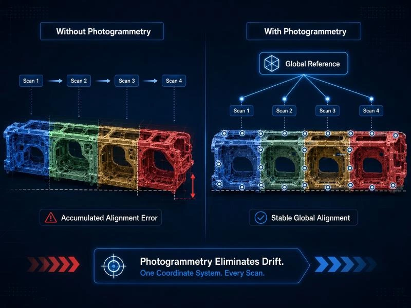
Large industrial parts often cannot be captured from one scanner position. The operator may need to move around the component and collect many overlapping datasets.
A simplified local alignment process may look like:
Scan A → Scan B → Scan C → Scan D → Scan E
Each scan region is connected to the next through overlapping geometry or reference markers. If small alignment differences occur at several stages, their influence may become more noticeable when comparing features located far apart on the complete component.
This challenge becomes more important when:
- The component extends across several meters
- Many scanner positions are required
- Opposite sides of the structure must remain dimensionally related
- The part contains long or relatively featureless areas
- Overall volumetric accuracy is more important than local detail alone
A Global Reference Changes the Alignment Strategy
With photogrammetry, reference targets distributed across the component are measured within one global coordinate system. These known coordinates can then be used during 3D scanning to connect different scan regions to the same measurement framework.
The alignment structure becomes closer to:
Global Reference → Scan A / Scan B / Scan C / Scan D / Scan E
This reduces dependence on a long chain of local registrations. Even when scan areas are captured from different positions, they can remain connected through common global reference points.
| Measurement Approach | Alignment Method | Large-Part Measurement Consideration |
|---|---|---|
| Sequential Local Alignment | Each scan region is mainly aligned to neighboring data | Small registration differences may become more significant across long measurement spans |
| Photogrammetric Global Reference | Multiple scan regions are related to one common coordinate network | Helps maintain more stable dimensional relationships across the complete component |
Why This Matters for Industrial Dimensional Inspection
Many large-part inspection tasks depend on more than the accuracy of an individual hole, edge, or surface. Engineers may also need to verify the dimensional relationship between features located on different areas of the structure.
For example, the inspection of a large automotive body structure may require verification of mounting points on opposite sides of the component. A large casting may require comparison of machined interfaces separated by several meters. Aerospace tooling may require dimensional control across its complete length rather than only within individual local areas.
In these situations, a stable global coordinate system helps ensure that detailed measurements are evaluated within the correct overall geometric relationship.
Photogrammetry Supports More Reliable Multi-Position Scanning
Photogrammetry does not replace the need for proper scanning technique, target placement, calibration, or data processing. Instead, it provides an additional level of spatial control for measurement tasks where the scanning area extends beyond a convenient local measurement volume.
By connecting different scanning positions to a common reference network, photogrammetry can help reduce accumulated alignment deviation and improve the consistency of large-scale 3D measurement results.
This is one of the key reasons industrial photogrammetry is often combined with 3D scanning when measuring full vehicles, large castings, heavy machinery, aerospace structures, and other components where both local surface detail and long-range dimensional accuracy are required.
Industrial Applications of Photogrammetry
Industrial photogrammetry is particularly valuable when components are too large for efficient measurement from a single position or when dimensional relationships must be maintained across a wide measurement area. Instead of focusing only on local surface detail, it provides a global reference that supports large-scale inspection, assembly verification, and 3D scanning.
The technology can be applied across automotive, aerospace, heavy machinery, energy, tooling, and other industries where large components require accurate dimensional control.
Automotive Manufacturing
Modern automotive manufacturing involves increasingly large and integrated structures. Full vehicle bodies, body-in-white assemblies, battery structures, stamping dies, and large castings may extend across several meters and contain critical mounting points distributed throughout the component.
Photogrammetry can establish a coordinate network across the complete structure before detailed scanning or inspection begins. This helps manufacturers verify dimensional relationships between distant features and supports multi-position measurement of large automotive parts.
Typical automotive applications include:
- Full vehicle dimensional measurement
- Body-in-white structure inspection
- EV battery tray and large structural component measurement
- Integrated aluminum casting inspection
- Automotive tooling and fixture verification
Aerospace Structures and Tooling
Aircraft components, assembly tooling, and aerospace structures frequently combine large dimensions with strict geometric requirements. Measurement may need to cover long distances while maintaining accurate relationships between holes, interfaces, edges, and assembly locations.
Photogrammetry provides a practical way to establish global reference coordinates across these structures. Detailed 3D scanning can then be carried out within the same measurement framework where higher-density surface information is needed.
Heavy Machinery and Large Fabricated Structures
Machine frames, construction equipment components, welded structures, and large housings can be difficult to move into conventional measurement environments. Their size may also require inspection from many different positions.
Industrial photogrammetry supports on-site measurement by allowing reference targets to be distributed across the structure and measured within one coordinate network. This can help with dimensional verification, assembly alignment, deformation analysis, and comparison between manufactured geometry and design requirements.
Energy and Large Industrial Components
Large components used in wind power, power generation, and industrial equipment may include long structures, large flanges, frames, housings, and fabricated assemblies. In these applications, the relationship between distant features can be as important as the geometry of an individual surface.
| Industry | Typical Components | Photogrammetry Value |
|---|---|---|
| Automotive | BIW, full vehicles, battery structures, large castings | Supports global dimensional verification across large structures |
| Aerospace | Aircraft structures, tooling, large assemblies | Maintains spatial relationships across long measurement spans |
| Heavy Machinery | Frames, housings, welded structures | Supports flexible multi-position and on-site measurement |
| Energy | Wind power and large industrial components | Creates a common reference for large-scale dimensional control |
When Should You Use Photogrammetry?
Photogrammetry is not required for every 3D measurement task. Small components or parts that can be captured efficiently within a limited measurement area may be measured directly with a 3D scanner. Its value becomes greater as the component size, number of scanning positions, and importance of long-range dimensional relationships increase.
Photogrammetry should be considered when one or more of the following conditions apply:
- The component is several meters long: A global coordinate network helps maintain dimensional relationships between distant areas.
- Many scanning positions are required: Photogrammetric targets can provide common reference coordinates throughout the measurement process.
- Overall dimensional accuracy is critical: Large components may require verification of relationships between features located far apart.
- The component cannot easily be moved: Portable photogrammetry supports measurement directly in workshops, production areas, or field environments.
- Large-scale assembly alignment is required: Global coordinates can support positioning and verification of multiple structural features.
- Local scan alignment alone is not sufficient: A global reference can provide additional control across long measurement spans.
When Photogrammetry May Not Be Necessary
For a small precision component, a handheld or stationary 3D scanner may already provide sufficient measurement coverage and accuracy without an additional photogrammetry step. The same may be true when only a small local region needs inspection or when the entire part can be scanned efficiently from a limited number of positions.
The decision should therefore be based on the actual measurement requirement rather than component type alone. Part size, tolerance, measurement range, required surface detail, number of scanning positions, and inspection environment should all be considered.
A practical rule is that photogrammetry becomes increasingly valuable when the measurement challenge shifts from capturing local geometry to maintaining accurate global relationships across a large object.
Industrial Photogrammetry for Large-Scale Measurement
Industrial photogrammetry differs from general image-based 3D reconstruction because its primary goal is reliable dimensional measurement. Systems designed for metrology applications use calibrated imaging hardware, dedicated measurement targets, scale references, and specialized software to calculate stable coordinates across large measurement volumes.
For manufacturers, the objective is not simply to generate a visually realistic 3D model. The measurement data must support engineering tasks such as dimensional inspection, alignment verification, assembly analysis, and integration with other 3D measurement systems.
What an Industrial Photogrammetry System Provides
A typical industrial workflow focuses on several core capabilities:
- Establishing accurate 3D coordinates across a large component
- Creating a global reference network for subsequent measurement
- Supporting flexible image capture from multiple positions
- Maintaining dimensional relationships over long measurement spans
- Integrating photogrammetric coordinates with detailed 3D scanning data
This makes industrial photogrammetry especially useful for components where a conventional local measurement approach would require many separate measurement positions.
VMetric for Large-Scale Industrial Measurement
VISION3D's industrial photogrammetry system is designed to provide a global measurement reference for large-scale industrial applications. The VMetric Series can establish target coordinates across large components and provide the reference framework required for subsequent dimensional measurement or detailed 3D scanning.
Rather than replacing a 3D scanner, the system is designed to address the large-volume part of the measurement task. It can be particularly useful for full vehicles, large castings, aerospace structures, machine frames, tooling, and other components where long-range dimensional consistency is important.
For applications requiring a dedicated handheld photogrammetry solution, the VMetric 20M photogrammetry system can be integrated into large-part measurement workflows to establish a stable global reference before detailed surface data is acquired.
From Global Coordinates to Complete Measurement Data
A complete large-part measurement process may therefore use two levels of data:
Global Photogrammetric Reference + Detailed Surface Measurement
The global coordinates describe how distant areas relate to each other, while the surface measurement provides the detailed geometry required for inspection and engineering analysis.
This separation of roles allows manufacturers to select the most appropriate measurement technology for each stage rather than relying on one system to perform every measurement function.
Using Photogrammetry with VScan Handheld 3D Scanners
For large components that require both global dimensional control and detailed surface capture, photogrammetry can be combined with a handheld 3D scanner. The photogrammetry system establishes the large-scale reference network first, while the scanner captures high-density geometry from individual areas of the component.
VISION3D's VScan M Series metrology-grade handheld 3D scanners can be used in this type of workflow when detailed measurement is required across complex or large industrial parts.
| Measurement Stage | System Role |
|---|---|
| Global Reference Setup | VMetric establishes target coordinates across the large component |
| Detailed Surface Capture | VScan captures dense geometry, holes, edges, contours, and local features |
| Data Alignment | Individual scanning areas are connected through the common global reference |
| Inspection and Analysis | The complete 3D dataset can be used for dimensional verification and CAD comparison |
For applications involving large components and high scanning efficiency, the VScan M17 handheld 3D scanner can be used to capture detailed geometry while working within the broader photogrammetric reference.
The combination is particularly useful when manufacturers need to measure a component that is both physically large and geometrically complex. Instead of sacrificing local detail for measurement range, the workflow combines photogrammetry for global positioning with 3D scanning for dense surface acquisition.
FAQ About Photogrammetry
What is photogrammetry in simple terms?
Photogrammetry is a measurement method that uses photographs taken from different positions to calculate the three-dimensional coordinates and spatial relationships of points on an object. In industrial applications, it is commonly used to establish accurate reference coordinates across large components.
How does photogrammetry create 3D measurements?
The system identifies the same targets or features in multiple images and analyzes their different viewing angles. Through triangulation, their positions can be calculated in three-dimensional space. Repeating the process across many targets creates a 3D coordinate network.
How accurate is photogrammetry?
Photogrammetry accuracy depends on factors including system calibration, image geometry, target distribution, measurement range, number of observations, environmental stability, and the equipment being used. Industrial metrology systems are designed around controlled measurement rather than general-purpose 3D visualization.
What is 3D photogrammetry used for?
Industrial 3D photogrammetry is commonly used for large-part dimensional measurement, global coordinate establishment, assembly verification, tooling inspection, and as a reference system for detailed 3D scanning.
What is the difference between photogrammetry and 3D scanning?
Photogrammetry is particularly effective at establishing global coordinates and spatial relationships over large measurement areas. A 3D scanner captures dense surface geometry and detailed features. For large industrial components, the two technologies can be combined rather than used as direct alternatives.
Why is photogrammetry useful for large objects?
Large objects often require measurements from many positions. Photogrammetry creates a common coordinate network across the complete object, helping maintain dimensional relationships between areas that may be several meters apart.
Can photogrammetry be combined with a handheld 3D scanner?
Yes. Photogrammetry can first establish the global reference coordinates, while a handheld 3D scanner captures detailed surface geometry. The scan data can then be positioned within the same reference framework to support large-scale, high-detail measurement.
Does photogrammetry help reduce accumulated measurement error?
Photogrammetry can help reduce dependence on long chains of local scan alignment by providing a common global coordinate network. This is particularly useful when many scan positions are required across a large component.
Conclusion
Photogrammetry turns multiple images into measurable three-dimensional coordinates by identifying common reference points and calculating their spatial relationships. In industrial applications, its greatest value is the ability to establish a stable global coordinate network across large measurement volumes.
For small components, direct 3D scanning may provide all the measurement data required. As component size and measurement span increase, however, maintaining consistent relationships between distant areas becomes more challenging. Photogrammetry provides an additional level of global reference that can support more reliable large-part measurement.
Photogrammetry and 3D scanning therefore serve different but complementary roles. Photogrammetry establishes the global spatial framework, while a 3D scanner captures the dense surface geometry required for detailed inspection and analysis.
By combining these technologies, manufacturers can measure full vehicles, large castings, aerospace structures, heavy machinery, tooling, and other large components while maintaining both overall dimensional consistency and detailed geometric information.
For industrial applications where measurement range and global accuracy are critical, the combination of VISION3D VMetric photogrammetry and VScan handheld 3D scanning provides a practical approach to large-scale 3D measurement.