Photogrammetry for Large Volume Measurement: Challenges and Solutions
As industrial components continue to increase in size and complexity, accurate measurement across large areas has become a major challenge for manufacturers. Full vehicles, aerospace structures, large castings, heavy machinery components, and industrial tooling often require measurement over several meters while maintaining reliable dimensional relationships between different areas.
Unlike small-part inspection, large volume measurement involves more than capturing surface details. Manufacturers need to ensure that distant features, assembly interfaces, and critical reference points remain accurately positioned within the same coordinate system.
Traditional measurement approaches may face limitations when dealing with large components because inspection often requires multiple setups, repeated measurements, and complex alignment processes. As measurement volume increases, maintaining consistent accuracy across the complete part becomes increasingly important.
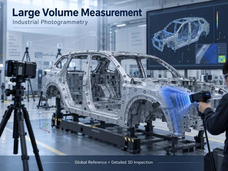
Industrial photogrammetry provides a solution by creating a global reference network based on multiple image observations and calculated 3D coordinates. This reference framework helps connect different measurement areas and supports more reliable large-scale dimensional analysis.
When combined with large-part 3D scanning, photogrammetry can provide both global measurement stability and detailed surface information. This combination allows manufacturers to inspect complex industrial components while improving alignment consistency, measurement efficiency, and overall inspection reliability.
This article explores how industrial photogrammetry improves large volume measurement, supports large-part 3D scanning, and creates reliable global references for industrial inspection.
Why Large Volume Measurement Is Challenging
Large volume measurement is more complex than traditional dimensional inspection because manufacturers need to maintain accuracy across an entire component rather than only verify individual features. As the physical size of a part increases, the relationship between distant areas becomes more difficult to control.
For large industrial components, measurement accuracy is not only determined by local surface capture. Engineers also need to ensure that features separated by long distances remain correctly positioned within the same reference system.
Large Measurement Areas Require Consistent Dimensional Control
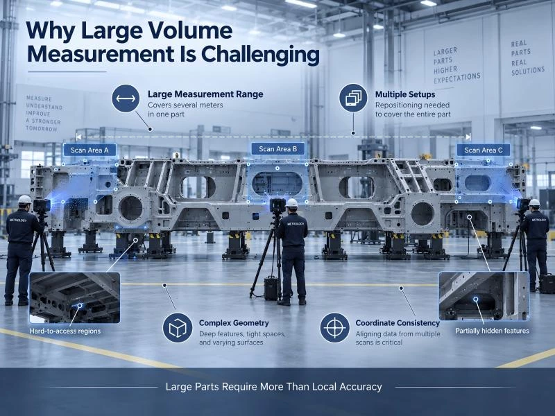
Small components can often be inspected within a limited measurement range using a single setup. However, large structures may extend across several meters and require multiple measurement positions to capture the complete geometry.
Typical large-volume measurement applications include:
- Full vehicle bodies
- Aircraft structures
- Large aluminum castings
- Heavy machinery frames
- Industrial tooling and fixtures
For these applications, manufacturers are not only concerned with the shape of individual surfaces. They also need to verify relationships between critical features, such as mounting points, assembly interfaces, and structural reference locations.
Multiple Measurement Setups Increase Alignment Requirements
Large components usually cannot be measured from a single position. A complete inspection workflow may require collecting data from different areas and combining these measurements into one complete dataset.
A typical large-part measurement process may involve:
| Measurement Challenge | Potential Impact |
|---|---|
| Multiple measurement positions | Requires accurate alignment between different areas |
| Long measurement distances | Makes overall dimensional consistency more important |
| Limited reference information | Can make coordinate relationships more difficult to maintain |
| Complex structures | Requires flexible inspection strategies and better planning |
Maintaining Global Accuracy Is Different from Local Accuracy
One of the biggest challenges in large-scale measurement is the difference between local accuracy and global accuracy.
A measurement system may capture a small area with excellent detail, but large components require the entire structure to remain accurate as a whole. For example, two mounting points located several meters apart must maintain the correct dimensional relationship, even if they are measured from different positions.
This requirement makes global reference control especially important for applications involving large industrial components.
Complex Industrial Components Create Additional Challenges
Many large components also include irregular surfaces, limited access areas, and complex geometries. These characteristics can make measurement planning more difficult because different regions may require different viewing angles or measurement positions.
Manufacturers often need inspection solutions that can provide:
- Large measurement coverage
- Stable coordinate references
- Flexible data acquisition
- Reliable dimensional relationships
- Integration with detailed 3D scanning workflows
As a result, large volume measurement requires more than simply collecting more measurement data. It requires a reliable reference framework that can maintain accuracy across the complete component.
Common Challenges in Large-Scale Measurement
Large-scale measurement involves more than increasing the scanning range of a measurement device. As component dimensions grow, manufacturers must consider how to maintain accurate spatial relationships, ensure reliable data alignment, and achieve consistent inspection results across the complete structure.
Different industries may face different measurement requirements, but the core challenges are often related to measurement volume, reference stability, and inspection efficiency.
| Challenge | Measurement Impact | Industrial Example |
|---|---|---|
| Large Measurement Volume | Requires accurate control of dimensional relationships across wide areas | Full vehicle bodies, aircraft structures, large machinery |
| Multiple Measurement Setups | Increases the need for reliable alignment between different measurement areas | Large castings, tooling, fabricated structures |
| Limited Reference Information | Makes it more difficult to maintain a stable coordinate system | Complex industrial components with large surfaces |
| Complex Geometry | Requires flexible measurement strategies for different surface areas | Irregular castings, welded assemblies, structural parts |
| On-Site Measurement Conditions | Requires portable and adaptable inspection solutions | Heavy equipment and large installed components |
Maintaining Coordinate Consistency Across Large Components
One of the main difficulties in large volume measurement is keeping all measured areas within the same coordinate framework. When a component extends across a large distance, features located at opposite ends must still maintain their correct dimensional relationship.
This is especially important for applications where multiple areas affect final assembly performance. For example, automotive structures may require accurate positioning between mounting interfaces, while industrial machinery components may require alignment between multiple functional surfaces.
Managing Multiple Measurement Positions
Large components often require measurement from different directions and locations. Each additional position introduces another data acquisition step that must be correctly connected with the overall measurement result.
A reliable large-scale measurement workflow must consider:
- Reference point distribution
- Measurement area coverage
- Data alignment consistency
- Overall dimensional verification
Without a stable reference framework, connecting multiple measurement areas can become more challenging as the size of the component increases.
Balancing Measurement Range and Surface Detail
Large industrial inspection often requires two different types of measurement information. Manufacturers need accurate relationships across the entire component, but they also need detailed surface data for specific features.
For example, a large casting may require overall dimensional verification while also requiring detailed inspection of holes, edges, and machined surfaces.
This creates a need for measurement solutions that can combine:
- Large-scale spatial reference
- Detailed surface capture
- Reliable data alignment
- Efficient inspection workflows
Addressing these challenges requires more than simply collecting additional measurement data. A reliable large-scale inspection process needs a stable reference system that connects different measurement areas and supports accurate analysis of the complete component.
How Industrial Photogrammetry Improves Large Volume Measurement
Industrial photogrammetry helps solve many large volume measurement challenges by creating a stable coordinate framework across the entire component. Instead of relying only on local measurements or sequential data alignment, the system uses a network of reference targets to establish consistent spatial relationships over a much larger area.
This makes it particularly useful for large industrial parts that require multiple measurement positions, long-distance dimensional verification, and integration with detailed 3D scanning.
Establishing a Global Reference System
The core advantage of industrial photogrammetry is its ability to create a global coordinate reference across a large measurement volume. Measurement targets are distributed over the component and captured from multiple positions, allowing their 3D coordinates to be calculated within one unified reference system.
This global reference helps manufacturers maintain consistent relationships between distant areas of the part, even when they are measured from different positions.
For example, when inspecting a large automotive structure, mounting points located several meters apart can still be evaluated within the same coordinate framework rather than treated as separate local measurements.
Improving Alignment Stability Across Multiple Measurement Areas
Large components often require many individual measurement positions. If each area is aligned only to the previous one, the process can become increasingly dependent on local registration quality.
A sequential alignment workflow may look like:
Measurement A → Measurement B → Measurement C → Measurement D
With photogrammetry, the relationship changes:
Global Reference → Measurement A / Measurement B / Measurement C / Measurement D
Each measurement area can be connected to the same global coordinate network. This reduces the dependence on long chains of local alignment and helps improve overall measurement stability across the complete component.
Supporting More Reliable Large-Part 3D Scanning
Photogrammetry is especially effective when combined with large-part 3D scanning. The photogrammetric network provides the large-scale reference, while the 3D scanner captures dense surface geometry from individual regions.
The two measurement levels serve different purposes:
| Measurement Level | Main Function |
|---|---|
| Global Photogrammetric Reference | Maintains dimensional relationships across the complete component |
| Detailed 3D Scanning | Captures holes, edges, surfaces, contours, and complex local geometry |
This combination allows manufacturers to inspect large structures without sacrificing detailed geometric information.
Improving Measurement Efficiency
Large volume measurement can become time-consuming when operators need to repeatedly reposition equipment, establish new local references, or manually combine separate datasets.
Industrial photogrammetry can simplify this process by creating the reference framework first. Once the global coordinate network has been established, subsequent measurements can use the same reference system throughout the inspection workflow.
This can help reduce repeated alignment steps and support more efficient measurement of large or difficult-to-move components.
Supporting More Consistent Industrial Inspection
For industrial quality control, measurement consistency is just as important as individual point accuracy. Manufacturers need repeatable inspection results that can be compared across production batches, assembly stages, or engineering revisions.
A global reference system provides a more stable foundation for dimensional analysis because different measurement areas remain connected within the same coordinate structure.
As a result, industrial photogrammetry can support:
- Large-part dimensional inspection
- Assembly and alignment verification
- CAD comparison
- Deformation analysis
- Tooling and fixture verification
- Multi-position 3D scanning
By combining global reference control with flexible data acquisition, industrial photogrammetry provides a practical way to improve the reliability and efficiency of large volume measurement.
Photogrammetry and Large-Part 3D Scanning Workflow
A large volume measurement project typically requires both global dimensional control and detailed surface information. Industrial photogrammetry and 3D scanning can be combined in a structured workflow so that each technology handles the measurement task it is best suited for.
The overall process can be summarized as:
Target Placement → Photogrammetric Measurement → Global Reference → 3D Scanning → Data Alignment → Inspection Analysis
Step 1: Establish Measurement Targets
Reference targets are distributed across the large component before detailed measurement begins. Their placement should provide sufficient coverage across the complete structure, including areas that will later be captured from different scanning positions.
For large automotive bodies, castings, tooling, or machinery frames, targets may be placed across both local features and distant areas so that the complete component can be connected within one coordinate network.
Step 2: Build the Global Coordinate Network
The photogrammetry system captures the targets from multiple positions and calculates their 3D coordinates. These coordinates establish the global reference used throughout the remaining measurement process.
At this stage, the primary objective is not dense surface capture. The goal is to create a reliable spatial framework that defines how different areas of the component relate to each other.
Step 3: Capture Detailed Geometry with 3D Scanning
Once the global reference has been established, a 3D scanner can capture the detailed surface geometry required for inspection. The scanner can move around the component and collect data from individual regions while using the photogrammetric targets as reference information.
Detailed scanning can capture features such as:
- Holes and mounting interfaces
- Edges and contours
- Complex freeform surfaces
- Machined areas
- Surface deformation
- Local geometric features
Step 4: Align and Analyze the Complete Dataset
Measurement data from different scanning positions can then be connected within the global coordinate framework. Engineers can use the completed dataset for dimensional inspection, CAD comparison, deformation analysis, or assembly verification.
| Workflow Stage | Main Purpose |
|---|---|
| Target Placement | Create reference coverage across the large component |
| Photogrammetry | Calculate global reference coordinates |
| 3D Scanning | Capture dense local surface geometry |
| Data Alignment | Connect multiple scanning areas within one coordinate system |
| Inspection Analysis | Evaluate dimensional deviation and manufacturing quality |
This workflow allows manufacturers to combine large measurement coverage with detailed geometric inspection without relying on a single measurement method for every stage.
Factors Affecting Large Volume Measurement Accuracy
Industrial photogrammetry can provide a stable foundation for large volume measurement, but final measurement quality still depends on how the system is configured and operated. Large components require careful control of the measurement network because errors that appear insignificant in a small local area may become more important across long distances.
The most important factors include target distribution, image geometry, system calibration, measurement distance, environmental stability, and the relationship between photogrammetry and subsequent 3D scanning.
Target Distribution and Coverage
Targets should be distributed across the complete measurement volume rather than concentrated in only one area. Good target coverage helps create stronger spatial relationships between different parts of the component.
Particular attention should be given to:
- Long sections of the component
- Areas between different scanning positions
- Edges and structural transitions
- Regions where dimensional relationships are critical
Image Geometry and Observation Angles
Photogrammetric accuracy depends not only on the number of images but also on how the targets are observed. Capturing the same targets from different positions and angles provides stronger triangulation geometry and improves coordinate stability.
Images taken from nearly identical directions may provide less useful geometric information than a well-planned set of observations surrounding the measurement area.
Measurement Range and Component Size
As the measurement volume increases, maintaining global dimensional accuracy becomes more demanding. Large structures may require additional targets, more observation positions, and better measurement planning to maintain reliable relationships across the entire component.
For this reason, measurement performance should be evaluated according to the complete working volume rather than only the accuracy of an individual local area.
Calibration and Environmental Conditions
Industrial photogrammetry relies on calibrated measurement hardware and controlled geometric relationships. Calibration quality directly affects coordinate calculation, while environmental conditions can influence measurement stability during large-scale inspection.
| Factor | Why It Matters |
|---|---|
| Target Distribution | Supports stable reference relationships across the full component |
| Image Geometry | Improves triangulation and coordinate calculation |
| Measurement Volume | Influences global accuracy requirements and inspection planning |
| System Calibration | Maintains reliable geometric measurement |
| Temperature and Vibration | May affect measurement consistency in industrial environments |
| 3D Scan Alignment | Determines how detailed surface data relates to the global reference |
For large volume measurement, reliable results depend on the complete measurement strategy. A high-performance device alone cannot compensate for poor target placement, limited image geometry, or an unstable measurement environment.
Applications of Industrial Photogrammetry in Large Volume Measurement
Industrial photogrammetry is most valuable in applications where components are physically large, difficult to move, or require accurate relationships between widely separated features. These characteristics are common in automotive manufacturing, aerospace, heavy machinery, energy equipment, and large tooling production.
Automotive Manufacturing
Automotive structures can extend across several meters while containing numerous mounting points, assembly interfaces, and geometric features that must remain correctly positioned relative to each other.
Large volume photogrammetry can support inspection of:
- Full vehicle bodies
- Body-in-white structures
- EV battery structures
- Large integrated castings
- Stamping dies and automotive tooling
By establishing a global coordinate reference, manufacturers can combine measurements from multiple positions while maintaining the dimensional relationship between distant areas of the vehicle structure.
Aerospace Structures and Tooling
Aerospace manufacturing frequently involves large components with demanding dimensional requirements. Aircraft structures, assembly fixtures, and large tooling may require inspection across long measurement spans while maintaining precise relationships between interfaces and reference features.
Photogrammetry can provide the global reference needed for multi-position measurement and can be combined with detailed 3D scanning where complex surface geometry must also be captured.
Heavy Machinery and Fabricated Structures
Large machine frames, construction equipment components, welded assemblies, and industrial housings can be difficult to inspect using fixed measurement equipment. In many cases, measurement must be performed directly in the workshop or production environment.
Portable industrial photogrammetry supports flexible measurement around these structures and can help with:
- Dimensional verification
- Assembly alignment
- Welding deformation analysis
- Machining allowance inspection
- Large-part 3D scanning
Energy and Large Industrial Equipment
Wind power components, power generation equipment, large flanges, structural frames, and other energy-industry components may require measurement across long distances that cannot easily be covered by a single local setup.
In these applications, photogrammetry provides a common measurement framework that supports dimensional control across the complete structure and can be integrated with additional inspection methods when more detailed surface information is required.
| Industry | Typical Large Components | Measurement Requirement |
|---|---|---|
| Automotive | BIW, full vehicles, battery structures, large castings | Global dimensional control and assembly verification |
| Aerospace | Aircraft structures, tooling, fixtures | Long-range dimensional consistency |
| Heavy Machinery | Frames, housings, welded assemblies | Flexible on-site and multi-position inspection |
| Energy | Wind power and large industrial components | Large-scale coordinate control and dimensional verification |
Across these industries, the common requirement is the same: manufacturers need to maintain reliable dimensional relationships across large structures while still obtaining the detailed measurement data required for quality inspection.
Photogrammetry Solution for Large Industrial Inspection
Large industrial inspection often requires more than a single measurement technology. Manufacturers may need global dimensional control across several meters while also capturing detailed geometry around holes, edges, machined surfaces, and complex freeform areas.
A practical large volume measurement solution therefore combines two complementary capabilities:
- Industrial photogrammetry for establishing a stable global coordinate reference
- 3D scanning for capturing dense and detailed surface geometry
This combination allows different measurement areas to remain connected within the same reference framework while providing the surface detail required for dimensional inspection and engineering analysis.
VMetric for Global Measurement Re ference
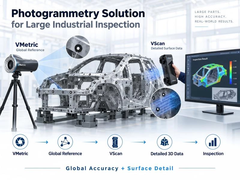
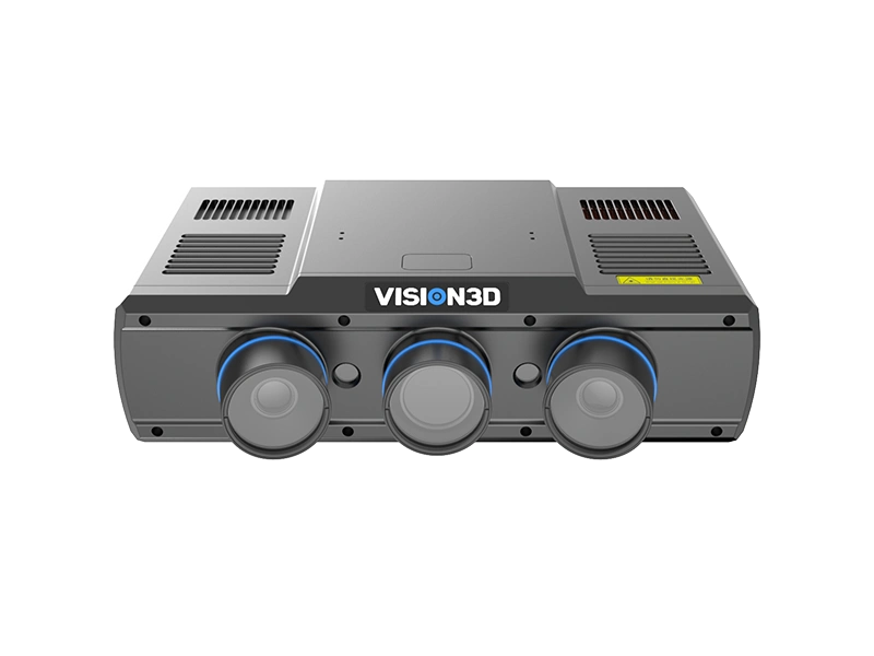
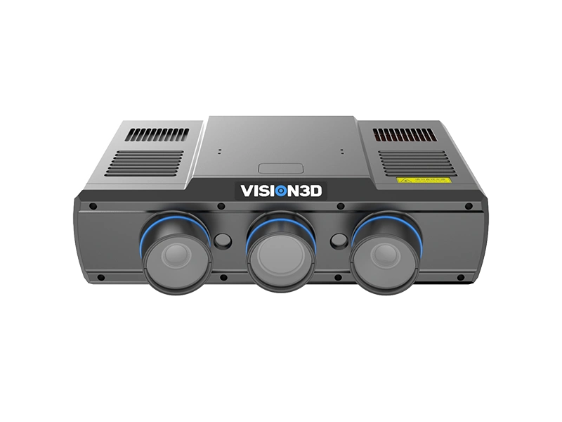
The VISION3D VMetric Series industrial photogrammetry system is designed for large-scale measurement applications where global dimensional relationships are critical.
By measuring reference targets distributed across a large component, VMetric can establish a coordinate network that supports subsequent inspection and 3D scanning. This is especially useful when the workpiece extends across a large measurement volume or requires data acquisition from many different positions.
Typical applications include:
- Full vehicle measurement
- Large automotive structures
- Aerospace components and tooling
- Heavy machinery frames
- Large castings and fabricated assemblies
VScan for Detailed Surface Measurement
Once the global reference has been established, detailed geometry can be captured using a metrology-grade handheld 3D scanner. The VScan M Series is suited to complex industrial components that require flexible scanning around large or difficult-to-access surfaces.
While photogrammetry controls the large-scale coordinate relationship, the 3D scanner captures the detailed surface information required for:
- CAD comparison
- Dimensional deviation analysis
- Hole and feature inspection
- Surface deformation measurement
- Reverse engineering
The resulting workflow can be summarized as:
VMetric Global Reference → VScan Surface Capture → Unified 3D Data → Inspection and Analysis
| Measurement Requirement | Recommended Role |
|---|---|
| Large measurement volume | Photogrammetry establishes the global coordinate network |
| Long-distance dimensional relationships | Global reference maintains consistency between distant areas |
| Complex surface geometry | 3D scanning captures detailed geometric information |
| Multi-position inspection | Photogrammetric references help connect different scanning areas |
| Dimensional inspection | Complete 3D data supports CAD comparison and deviation analysis |
For large industrial components, the objective is not simply to increase scanning range. A reliable measurement solution must maintain global dimensional consistency while still capturing the detailed geometry required for inspection. Combining industrial photogrammetry with handheld 3D scanning provides a practical way to achieve both.
FAQ About Large Volume Measurement and Photogrammetry
What is large volume measurement?
Large volume measurement refers to dimensional inspection performed across large components or measurement areas that may extend several meters. Typical applications include full vehicles, aerospace structures, heavy machinery, large castings, tooling, and fabricated assemblies.
Why is large-scale measurement more difficult than small-part inspection?
Large components usually require multiple measurement positions and wider measurement spans. The main challenge is maintaining reliable dimensional relationships between distant areas while combining data collected from different locations.
How does photogrammetry improve large volume measurement?
Photogrammetry establishes a global coordinate network across the complete component. Different measurement areas can then be referenced to the same coordinate system, helping improve alignment stability and overall dimensional consistency.
Can photogrammetry be combined with a 3D scanner?
Yes. Photogrammetry can provide the global measurement reference, while a 3D scanner captures dense surface geometry. This combination is useful when a large component requires both long-range dimensional accuracy and detailed local inspection.
Does photogrammetry improve volumetric accuracy?
Photogrammetry can help improve the consistency of measurements across large volumes by reducing dependence on long chains of local alignment. Final volumetric accuracy still depends on system calibration, target distribution, image geometry, measurement range, environmental conditions, and the overall measurement strategy.
What types of parts benefit most from industrial photogrammetry?
Industrial photogrammetry is particularly useful for large or difficult-to-move components such as vehicle bodies, aerospace structures, large castings, machinery frames, tooling, fixtures, and other structures that require measurement from multiple positions.
Is photogrammetry necessary for every large-part 3D scanning project?
No. Some parts can be measured effectively using a 3D scanner alone. Photogrammetry becomes more valuable when the component is large, many scanning positions are required, or accurate relationships between distant features are critical to the inspection result.
Conclusion
Large volume measurement presents challenges that go beyond capturing detailed surface geometry. As component size increases, manufacturers must maintain accurate dimensional relationships across long distances, connect data from multiple measurement positions, and ensure that the complete structure remains within one consistent coordinate framework.
Industrial photogrammetry addresses these challenges by establishing a global measurement reference across the component. This reference can improve alignment stability, support multi-position inspection, and provide a reliable foundation for large-scale dimensional analysis.
When combined with 3D scanning, photogrammetry provides a complementary measurement workflow. The photogrammetric system manages global spatial relationships, while the 3D scanner captures the detailed geometry needed for CAD comparison, dimensional inspection, deformation analysis, and other engineering tasks.
For automotive structures, aerospace components, heavy machinery, large castings, tooling, and other oversized industrial parts, this combination provides a more practical approach to achieving both large measurement coverage and detailed geometric inspection.
By integrating VMetric industrial photogrammetry with VScan handheld 3D scanning, manufacturers can build a large volume measurement workflow that combines reliable global references with detailed surface data for more efficient and consistent industrial inspection.